29
4
1. Safety features and safety precautions
You have chosen a meter which offers you a very high degree of safety.
This meter Gamma 20 is manufactured and tested in compliance with the
safety standard IEC 61010-1:2001 / DIN EN61010 -1:2001.
In case of incorrect use or careless handling, the safety of both user and
multimeter is not assured.
To maintain the safe and proper condition of the meter and to ensure their safe
operation, it is absolutely necessary to carefully and completely read these
operating instructions before using any meter. These instructions must be
followed in all respects.
For your safety and for protection of the meter, this meter is fitted with an
Automatic terminal Blocking System It is coupled with the function selector
switch which blocks the terminal sockets not necessary for measurement.
Please note the following safety precautions:
lThe meter must be operated only by persons who understand the
danger of shock hazards and know how to apply safety precautions.
Shock hazards exist wherever voltages of more than 30V (TRMS) can
appear.
lDo not work alone in shock hazardous environment while carrying out
measurement.
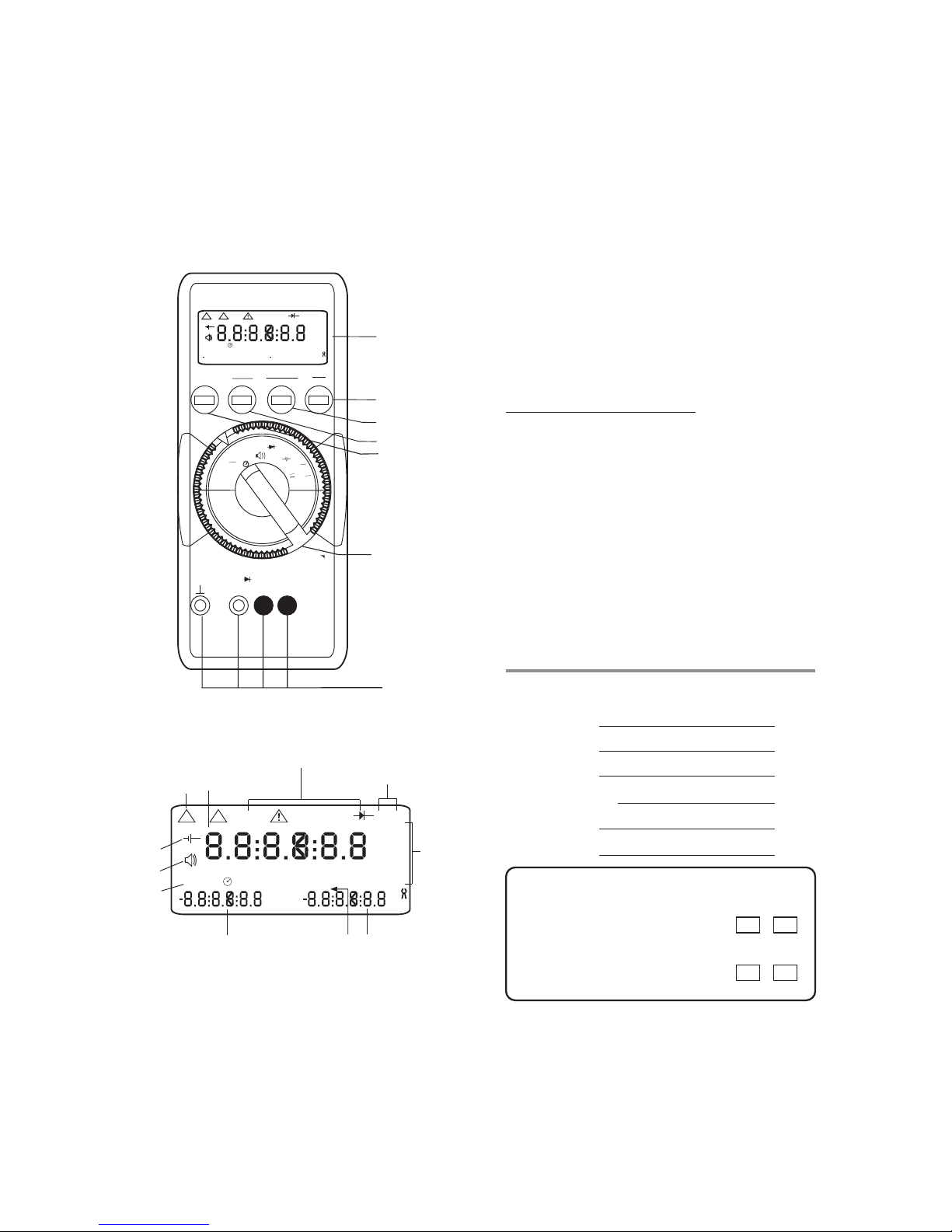
lThe maximum permissible voltage between terminal Socket (7) and
ground is 1000 V.
lTake into account that unexpected voltages can occur on device under
test (e.g. defective instrument). Capacitors may be charged to a
dangerously high voltage, for instance.
lVerify that the test leads are in good condition, e.g. no cracked
insulation, no open circuits in the leads or connectors.
lThis meter must not be used for measurements on circuits with corona
discharge (high voltage).
lBe particularly careful when measuring on HF circuits. Dangerous
composite voltages may exist there.
lMeasurements under moist environmental conditions are not Permitted.
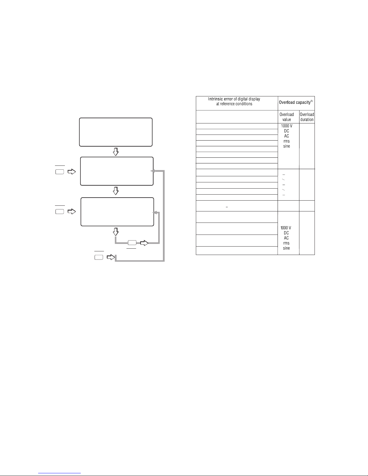
lDo not exceed the permissible overload limits of the measuring ranges.
See Table “Measuring ranges” under “15. Specifications”.
lAll current measuring ranges, are fused. The maximum permissible
voltage of the measuring circuit (=nominal voltage of the fuse) is1000 V
AC/DC in “mA” ranges, “A” ranges.
lYou must only use the meter in power systems, when the current circuit
is protected by a fuse or a circuit breaker of 20 A, and when the nominal
voltage of the system does not exceed 1000V.
For safe voltage measurements on power systems, up to 1000V we
recommend the KS 30 measuring adapter, which is available as accessory.
Its internal resistance limits the measuring current in the case of over voltage
and incorrect operation and safely suppress sparking from spark gaps. Also
refer to Section “7.1Voltage measurement on electrical systems up to 1000V
with the KS 30 measuring adapter”.
Fuse replacement
ŸOpen the meter same as for battery replacement
ŸRemove the blown fuse, e.g. with the aid of a probe, and replace it with a
new one.
Permissible types
Øfor current measuring ranges up to 300 mA:
FF (UR) 1.6A /1000 V AC/DC; (10 KA); 6.3 mm x 32 mm
Øfor the 10A current measuring ranges:
Type FF(UR) 16A/1000V AC/DC; (30kA); 10mmx38mm
Caution :
Absolutely verify that only the specified fuse is installed!
If a fuse of other cut-out capacity, other nominal current or other switching capacity
is used, a dangerous situation exists for you, and there is danger of damaging
protective diodes, resistors or other components.
The use of mended fuses or shorting of the fuse holder is not permissible.
16.3 Case
Special maintenance of the case is not required. Take care that the surface
between the connection sockets is clean. For cleaning take a moist cloth.
Avoid scrabbing.
17. Repair and replacement parts Service
When you need service, please contact :
Sifam Tinsley Instrumentation Ltd.
Central Buildings, Woodland Close,
Old Woods Trading Estate,
Torquey, Devan, England, TQ27BB
Website: www.sifamtinsley.com/uk
Contact Number: +44(O) 1803 615139
E-mail: info@tinsley.co.uk
Sifam Tinsley Instrumentation
3105, Creekside Village Drive,
Suite No 801,Kennesaw,
Georgia 30144
Contact Number: +1.404.736.4903
Web: www.sifamtinsley.com
18. Appendix
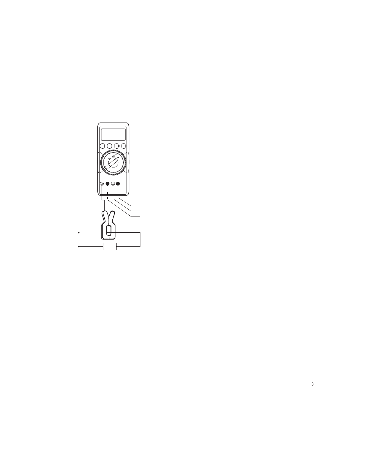
18.1 AC current measurement with (clip-on) current transformers
18.1.1 Transformer output mA/A
Caution:
If current transformers are operated with an open circuit on the secondary
side, e.g. due to defective or disconnected leads, a blown fuse In the meter, or
a wrong connection, dangerously high voltages can occur at the connectors.
Therefore, verify that the current circuit of the meter and the secondary
winding of the transformer connected to the meter form an intact circuit.
Connect the transformer to the sockets ^ and mA and/or A.
The maximum permissible operating voltage is the nominal voltage of the
current transformer. When reading the measured value, take into account the
transformer ratio and the additional error in indication.
18.1.2 Transformer output V
Several transformers are fitted with a voltage output (designation mV/A). The
secondary output must therefore be connected to the connection sockets ^
and V.