ED.03.16 REV.00
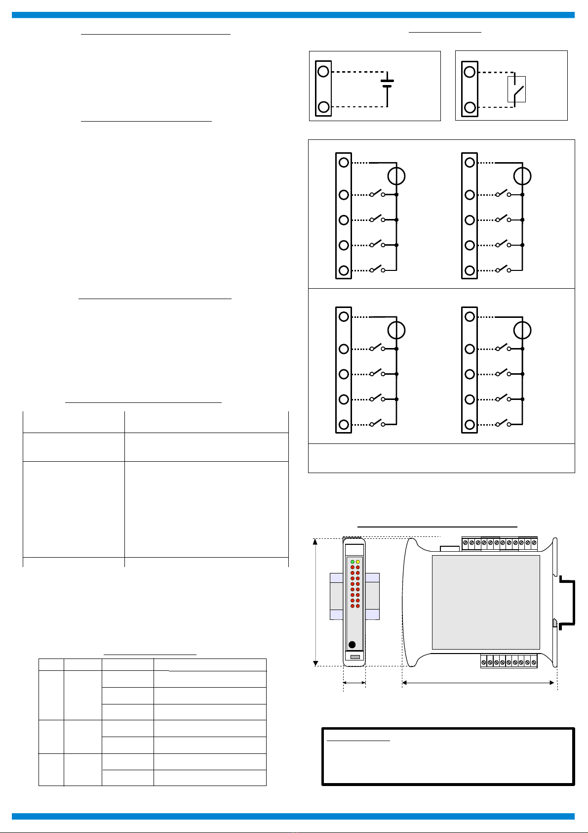
CONNECTIONS
POWER SUPPLY
+
-
10÷30 Vdc
O
P-V
+V
INIT
ON: short-circuit
to GND
Q
PV-
INIT
DIGITAL INPUTS
MECHANICAL DIMENSIONS (mm)
120
22.5
100
“ SS 8148 “
Note: the device is provided with default configuration as:
IP address: 1 2.168.1.100
Modbus address: 1
HOW TO ORDER
NOTES:
th input chann ls from 0 to 7 ar not isolat d b tw n th m .
th input chann ls from 8 to 15 ar not isolat d b tw n th m .
Th group of input chann ls 0÷7 is isolat d from th group of input chann ls 8÷15.
F
E
DI0
G
H
I
DI1
DI2
DI3
J
E
DI4
L
M
N
DI5
DI6
DI7
COM COM
2
1
DI8
3
4
5
DI9
DI10
DI11
6
1
DI12
7
8
9
DI13
DI14
DI15
COM1 COM1
GROUP DIGITAL INPUTS 0÷7
GROUP DIGITAL INPUTS 8÷15
INSTALLATION INSTRUCTIONS
The device is suitable for fitting to DIN rails in the vertical position.
It is always a good thing to space the devices together 5mm. Make sure that sufficient air
air flow is provided for the device avoiding to place raceways or other objects which could
obstruct the ventilation slits. Moreover it is suggested to avoid that devices are mounted
above appliances generating heat. Install the device in a place without vibrations. It is
also suggested to avoid routing conductors near power signal cables and to use shielded
cables for connecting signals.
MODULE CONFIGURATION
To configure the SS8000 series devices, it is necessary to enable the INIT mode. This
mode allows you to access the device with the following default parameters :
IP Addr ss:192.168.1.174 (DHCP disabled), or IP provided by DHCP (if enabled)
Modbus Addr ss: 245
To enter the INIT mode follow these steps:
- Turn off the device;
- Connect the INIT terminal to the -V terminal as shown in figure.
- Turn on the device and connect with an internet browser to the device using the default
parameters listed above and using the default login credentials:
Us rnam : admin
Password: admin
To exit INIT mode follow these steps:
- Turn off the device;
- Remove the INIT connection;
- Turn on the device and connect with the new parameters.
RESET FUNCTION- “P” BUTTON
If it is necessary to restore the default device parameters, with device powered and not in
INIT condition, push the front located “P” button for at least 5 seconds.
The green led PWR will switch-off, the yellow led STS will become orange and the reset
of the device will occur. When the reset procedure will be finished, both the leds will set
back to the default condition and the following parameters will be loaded :
Ethernet: Username: admin
- IP Address: 1 2.168.1.100 Password: admin
- Subnet Mask : 255.255.255.0
- Gateway Mask: 1 2.168.1.1 Modbus Address: 1
Device not powered
LIGHT SIGNALLING
LED COLOUR STATE DESCRIPTION
PWR GREEN ON
OFF
Device powered
STS YELLOW OFF Device in RUN modality
ON Digital Inputs High Level (1)I n RED
OFF Digital Inputs Low Level (0)
BLINK Device in INIT modality
BLINK Watchdog alarm
MAPPATURA REGISTRI MODBUS
R gist r
Position
Winlog
Syntax D scription Acc ss
40007 3:06 Node ID R/W
40011 3:10 System Flags R/W
40013 3:12 Watchdog timer R/W
40032 3:31 Digital Inputs RO
40033 3:32 Digital Inputs Rise Latch R/W
40034 3:33 Digital Inputs Fall Latch R/W
40035 3:34 Freq. Digital Input 0 RO
40036 3:35 Freq. Digital Input 1 RO
40037 3:36 Freq. Digital Input 2 RO
40038 3:37 Freq. Digital Input 3 RO
4003 35:38 32 bit Counter Digital Input 0 R/W
40041 35:40 32 bit Counter Digital Input 1 R/W
40043 35:42 32 bit Counter Digital Input 2 R/W
40045 35:44 32 bit Counter Digital Input 3 R/W