Siebeck JET Series Manuel d'exploitation
Translation of the original operating manual
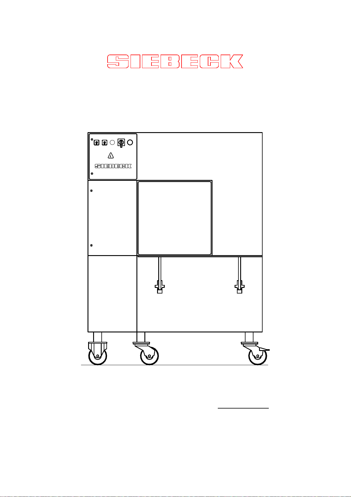
JET 2000 Strapping Machines
Model range JET-OB
123
4
01
1
0
SIEBECK GMBH D - 69412 EBERBACH
Telephone 00496271-9208 0 Fax 00496271-9208 88

2
Contents
Page
Foreword 3
Warranty 4
Technical data 5
Safety 6
Set-up, start-up, maintenance 7
Control elements 8
Inserting the cord 9 - 10
Operating the machine 11
Zero test / adjustment 12
Stripper setting 13
Faults and their causes 14
Knot - story 15 – 16
Recommended stock of spare parts 17
Spare parts – lists 18 -38
Mechanical components
Electrical components
Knotting unit
Wiring- and circuit diagram 39
IMPORTANT!
Read this manual carefully. This is compulsory for anyone
operating, servicing or monitoring this machine.

3
Foreword
This machine has been built in accordance with the state of the art, and
pursuant to worker protection and accident prevention regulations, such
that under normal proper use, there is no danger to life and limb of the
user or of third parties.
Any person in the user’s company, who is involved with the set-up,
start-up, operation, servicing and repair of this machine must have
read and understood this instruction manual, and in particular the
chapter on "Safety".
Customer-specific changes, restrictions or extensions and the resulting
safety-technical consequences shall be the responsibility of the user
company.
If this machine is sold or set up elsewhere, then this instruction manual
must be given to the new owner or the new user. Additional copies may
be ordered from the address given below.
SIEBECK GmbH
PO Box 1145
D - 69401 Eberbach
Telephone 00496271-92080
Fax 00496271-920888
www.siebeck.de

4
WARRANTY
All the machines that have been manufactured in our
production facilities have a 12-month warranty from the
start-up, or 18 months after the delivery. This warranty
relates to material and manufacturing defects.
The warranty covers all parts, with the exception of wear
and tear parts and parts, which are replaced as a result
of normal wear in the maintenance. Working time and
breakdowns are not included in our warranty obligation.
Should damage to the machine occur, through the use of
inappropriate strapping material, explicitly advised
against by us, this warranty shall not apply.
All claims must be made in writing. A precise description
of the cause of the damage and the part and machine
number must also be added. Once the warranty claim
has been accepted by us, the faulty part must be
returned to us.
This warranty is only valid if
original parts without any modification are used.
5
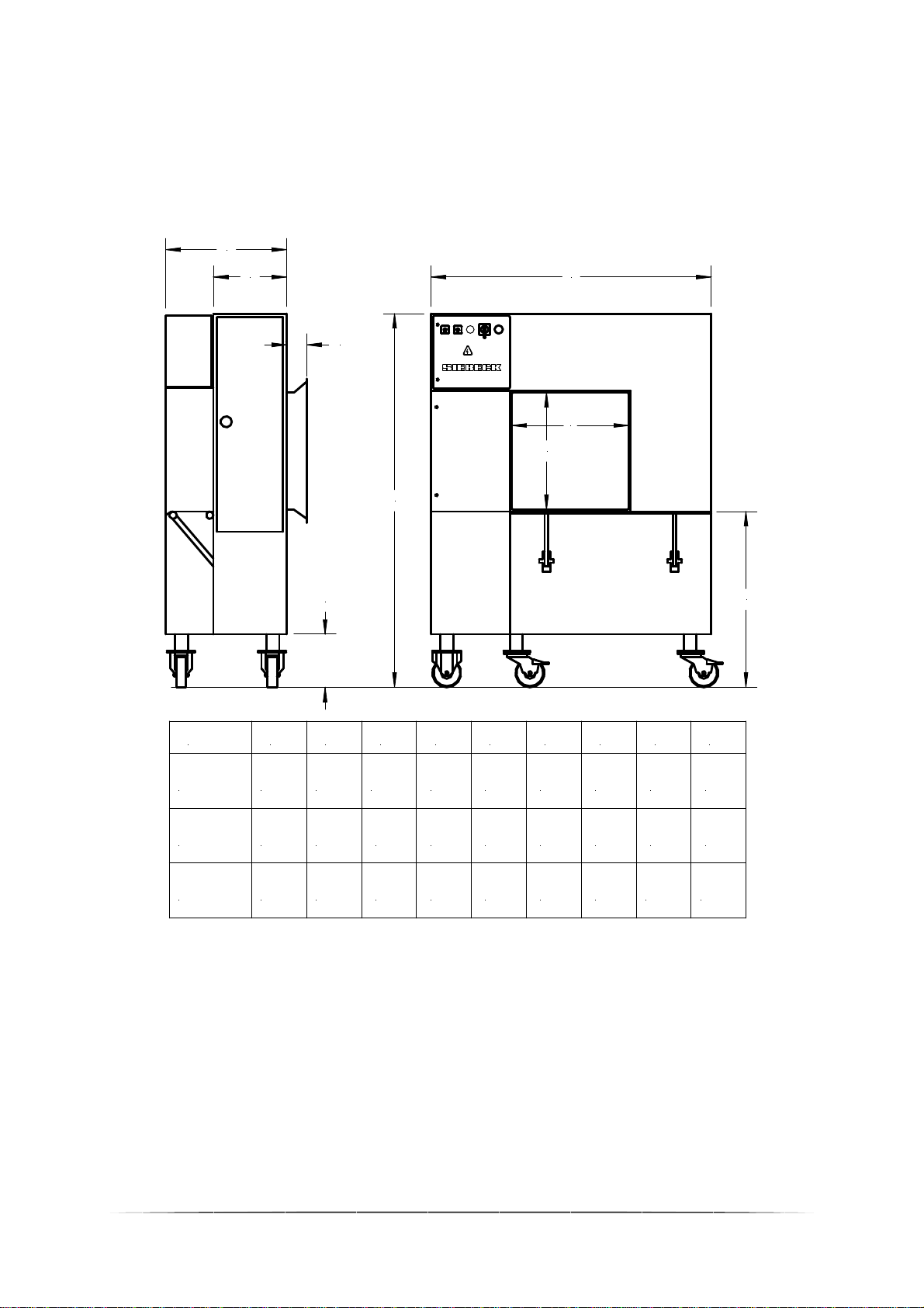
Technical data
Machine dimensions:
Typ
OB50
OB65
OB100
2040 1530 660
A B C D E F G H
400 960 290 650
1810 1220 660 400 955 290 110 500
110
J
500
650
2515 2220 660 400 920 290 110 1000 1000
123
4
01
1
0
A
B
CD
E
G
F
HJ
all dimensions in mm – subject to change
Machine capacity: 25 to 45 cycles per minute (depending on machine type)
Machine weight: OB 50 – 260 kg / OB 65 – 290 kg / OB 100 – 460 kg
Sound pressure level: 70 dB (A)
Electr. connection value: 230/400 Volt / 3 phase alternating current / 50 Hz / 1 Kw

6
Safety!
1.
The European standard EN 60204-1 requires that power be
supplied via an appropriate plug and socket device. Connecting the
power supply cable directly, without a plug to a power distributor is
therefore prohibited.
2.
The safety limit switches 4S1 and 4S2 prevent the machine from
starting when the side door is open. This safety device must be
checked before each start-up to ensure it is working.
Procedure:
Open door, do not reach into the inside of the machine (!),
Then activate foot switch. Machine must not start.
3.
Remove the mains plug when carrying out any maintenance and
cleaning works
4.
Always remove the mains plug when inserting a new cord reel,
and when threading the cords.

7
Set-up and start-up
Make sure the operating voltage is correct before starting up the
machine.
Operating voltage:
Unless otherwise specified, the machine is set on delivery ex works at
400 Volt alternate current 50 Hz.
Measure local mains voltage and
compare with the specification on the rating plate. Check for proper
grounding. Follow local EVU regulations. Maximum back-up fuse 16
amp.
Direction of rotation:
Connect the machine with a plug to the mains. Set on-off switch to
position "1". If the indicator light does not light up, the built-in phase
sequence relay locks the power supply, due to an incorrect direction of
rotation. For correct direction of rotation, exchange the two phase wires
in the plug.
Service and Maintenance
Maintenance-free, needle bearing-mounted track rollers, capped deep-
groove ball bearings, and other low-maintenance and wear-resistant
components reduce the amount of care and maintenance to a minimum.
We recommend cleaning the machine (do not use compressed air) every
week and lubricating all moving parts, especially the parts of the knotting
unit every week. The cord guide rollers and the bearing of the return arm
should also be oiled every week and checked for ease of movement (use
only non-resinous oils).
IMPORTANT!
Remove the mains plug when carrying out any maintenance and
cleaning works!

8
Control elements
On the control panel cover on the front of the machine, you will find the
following control elements:
123
4
01
1
0
A BCD
A On- off switch
Switch position ”0“ - Machine ”off“
Switch position “1“ - Machine ”on“
B Indicator light - signals the presence of voltage,
and the correct direction of rotation
C Selector switch (1-4) -for single- to multiple strapping
D Selector switch (0 / 1)
Switch position ”0“ - Normal operation
Switch position ”1“ - continuous strapping
Keep foot switch activated, the
strapping cycles are automatically triggered,
between the individual cycles, a downtime
of 0.5 sec is programmed at the factory.
On the inside back wall of the machine accessible when the side door is
open:
Push button
(on the side doors)
-
constant activation ventilates the brake
of the strapping arm or ring motor. The ring
can be turned manually to thread the line
more easily.
Push button
(on the knotting unit)
-
brief constant activation sets the
knotting unit to “tip operation”.

9
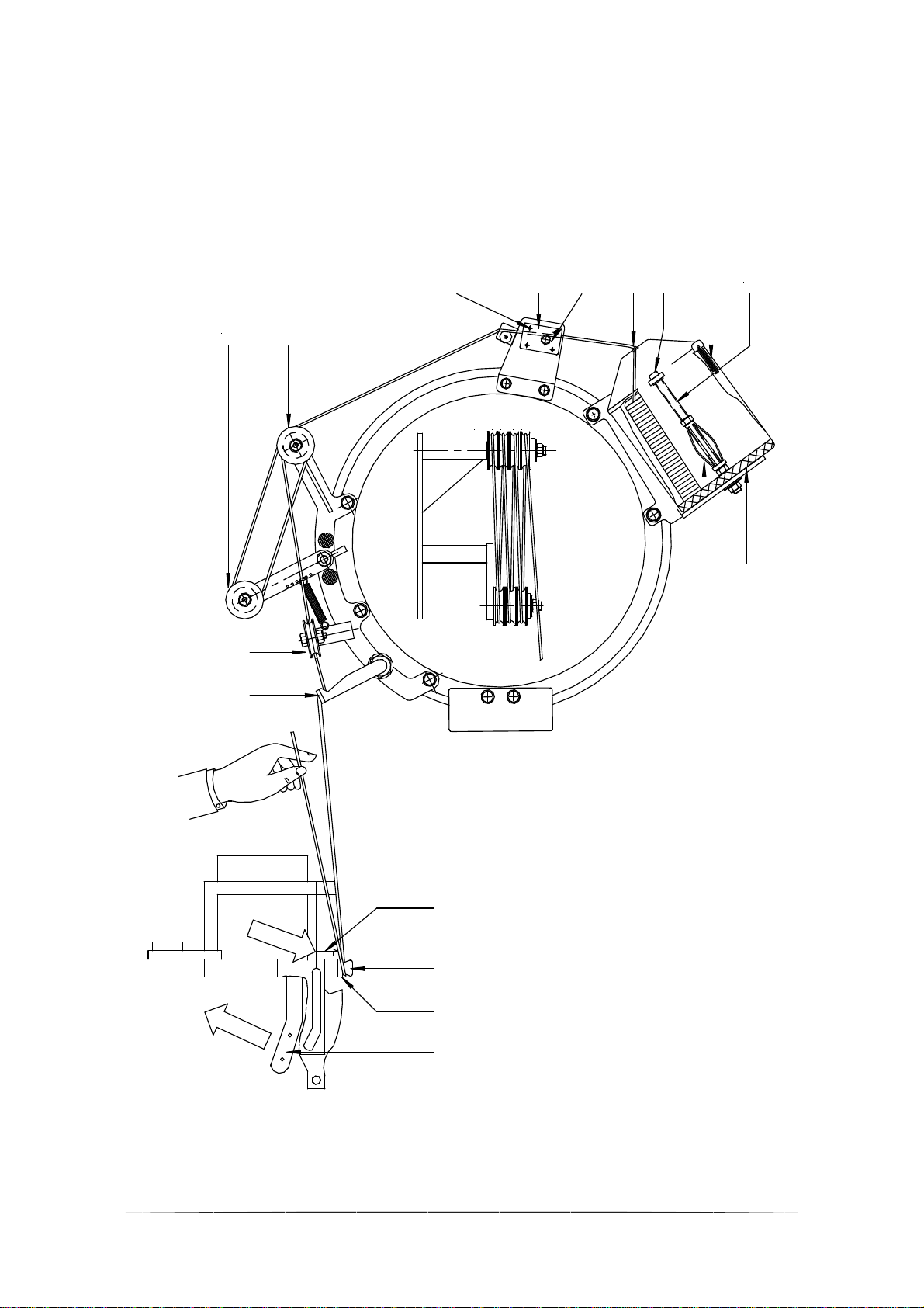
Inserting the cord
When the machine leaves our premises, it is fully threaded with a piece
of cord. Carefully study the course of the cord and you will be able to
understand the following description more easily.
Proceed as follows based on the threading diagram opposite:
- Loosen the spring cap (A) on the reel case and fold lid back
- Remove fastening nut (B) for cord reel
- Insert cord reel and press against the foam rubber inlay (D). It is
important to ensure that the paper case of the cord reel is sitting
tight on the expanding mandrel (E). Screw fastening nut (B)
and turn onto the paper case until the foam rubber bulges.
- Guide the start of the cord through the opening (F) in the reel case
cover and close cover via the spring cap (A).
- Insert cord into the thread brake (G). Ensure that the cord ends up
between the two pins (H) and the shaft of the hexagon screw (I)
(see Figure).
- The next cord guides are designed as rollers. Thread the cord in
the following number sequence:
L1 – K2 – L3 – K4 – L5 – K6 – L7 - M
- Guide the cord through the bore (N) at the end of the strapping arm
tube.
- Inserting the cord into the knotting unit:
Lay the cord with your left hand around the clamp (O), from bottom
to top. With your right hand, activate the clamp-ventilator lever (P)
in the direction of the arrow. While the left hand holds the cord
tightly, the cord ends up between clamp (O) and clamp housing
(R). Once the clamp – ventilator lever is released (P), the cord is
clamped. With the right hand, press the cutter lever (S) forward in
the direction of the arrow, the cord is cut.
IMPORTANT! Check the cord rollers and the return arm for ease
of movement each time you thread and oil if
necessary.
10
Inserting the cord
1 3 5 7
246
L
K
M
N
K L
HGIFBAC
E D
S
O
R
P
Ce manuel convient aux modèles suivants
5
Table des matières
Autres manuels Siebeck Équipement d'emballage


