5
SICK MSL
8 007 653/09-04-01 Technical Descrip ion • MSL © SICK AG • Safe y Sys ems • Germany • All righ s reserved
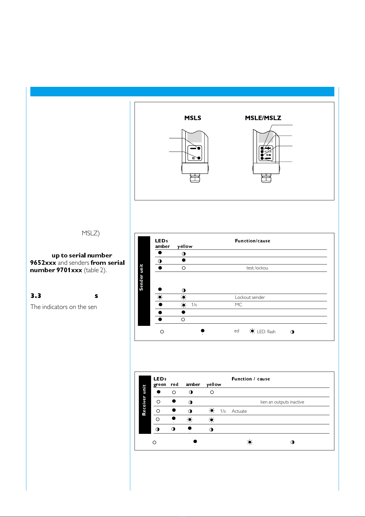
The posi ion of he ligh beams is
indica ed by a marking on he
housing.
Synchronisa ion be ween sender
uni and receiver uni is achieved
op ically, by means of a pre-defined
encoded sequence, hus elimina ing
he need for galvanic connec ion
be ween sender and receiver.
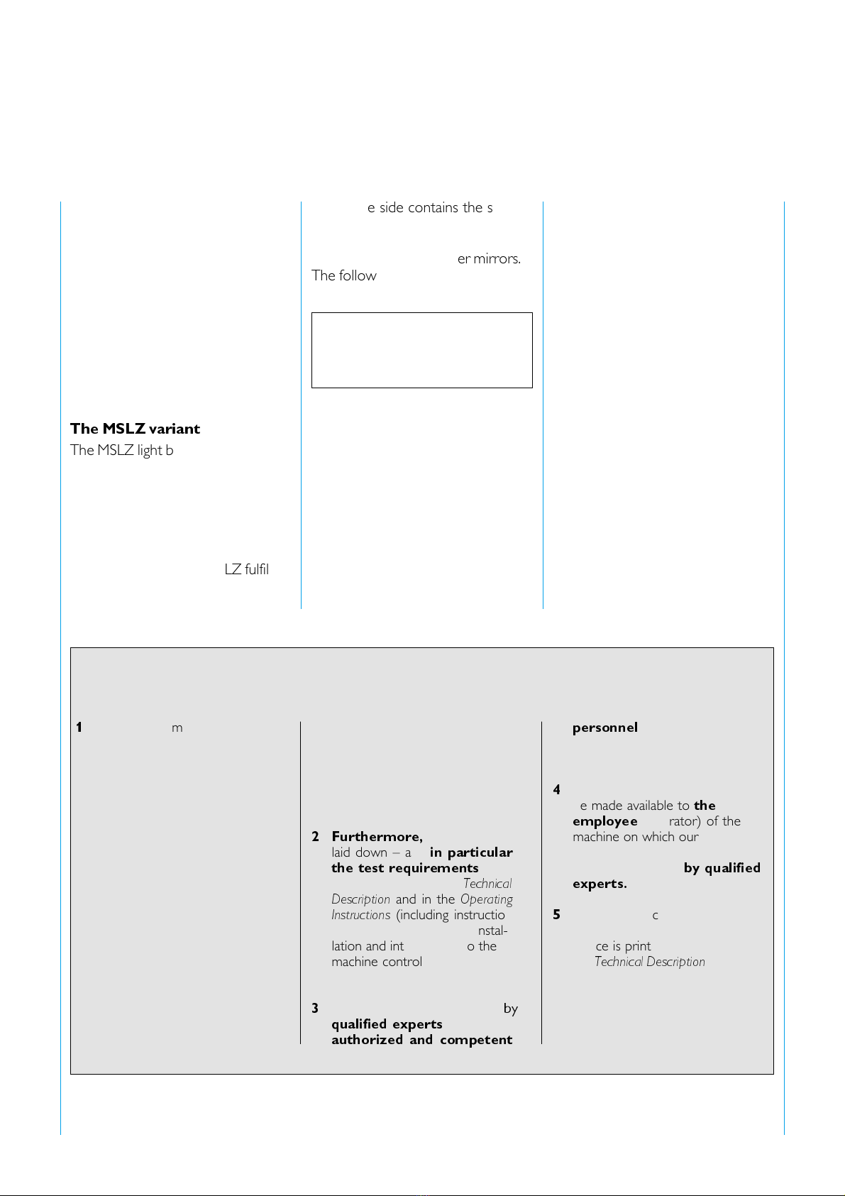
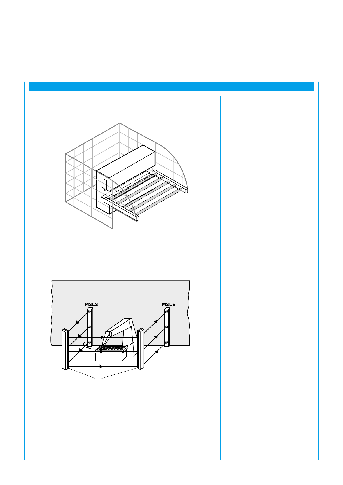
The MSLZ variant
The MSLZ ligh barrier, like he MSL
is a con ac less pro ec ion
ins alla ion – bu wi h one passive
side and one ac ive side (
fig. 2
). I is
sui able for access con rol and
danger zone pro ec ion wi h a pas-
sive mirror side, and a maximum
dis ance of 7.5 m. The MSLZ fulfils
he pr EN 50 100 (pr EN 61 496)
regula ions, safe y ca egory 4.
2.2 Intended use of the
device
The MSL mul ibeam safe y ligh barrier
may only be used as specified in
sec ion
2.1, Areas of use of he device
.
If i is used in any o her way, or if i is
modified in any way – including during
ins alla ion and moun ing – SICK AG
shall no be held liable for any
warran y claims arising.
2.3 General safety instructions and precautions
1
Ins alla ion, commissioning, use and
rou ine echnical checking of he
non-con ac safe y device is sub-
jec o na ional and in erna ional
regula ions and s andards, in
par icular:
‡ Regula ions derived from he
Machinery Direc ive 98/37
EC
‡ Regula ions derived from he
Use of Equipmen Direc ive
89/665 EEC
‡ Relevan safe y regula ions
‡ Applicable acciden
preven ion regula ions and
safe y rules.
The manufac urers and users of
he machinery on which our safe y
devices are used are solely
responsible for ascer aining all
applicable safe y s andards and
regula ions from he compe en
au hori ies and for ensuring
compliance wi h hose s andards
and regula ions.
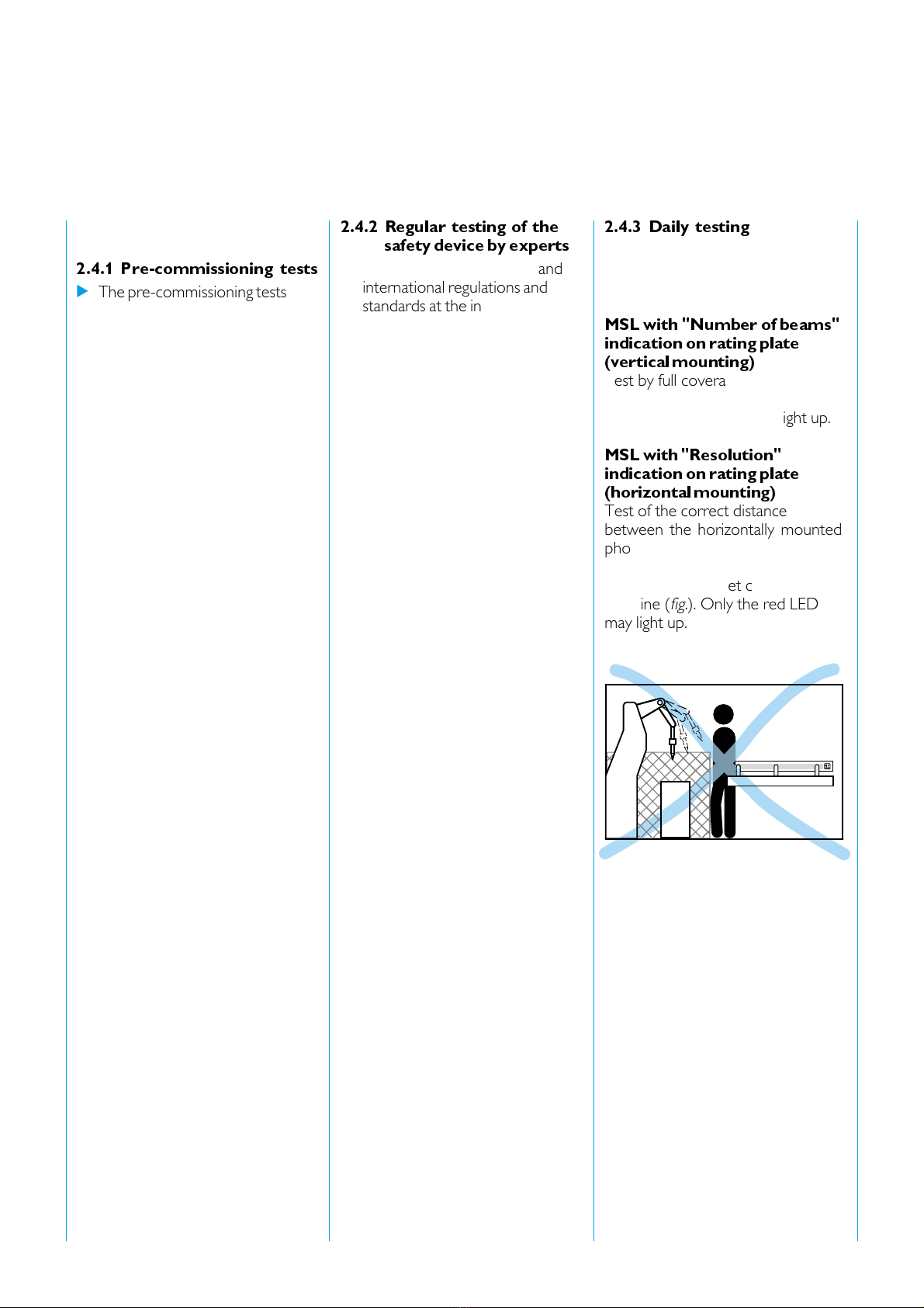
2 Furthermore,
he ins ruc ions
laid down – and
in particular
the test requirements
(see
Tes ing
) se ou in his
Technical
Description
and in he
Operating
Instructions
(including ins ruc ions
rela ing o use, moun ing, ins al-
la ion and in egra ion in o he
machine con rol sys em) – mus be
followed.
3
The es s mus be performed
by
qualified experts
or by
authorized and competent
personnel
and mus be
documen ed in such a way as o
be verifiable a any ime.
4
The Opera ing Ins ruc ions
mus
be made available o
the
employee
(opera or) of he
machine on which our safe y
device is used. The employee
mus be ins ruc ed
by qualified
experts.
5
The es pro ocol according o he
use of he non-con ac safe y
device is prin ed a he end of
his
Technical Description
.
Accep ance es ing is performed
on he basis of ha pro ocol.
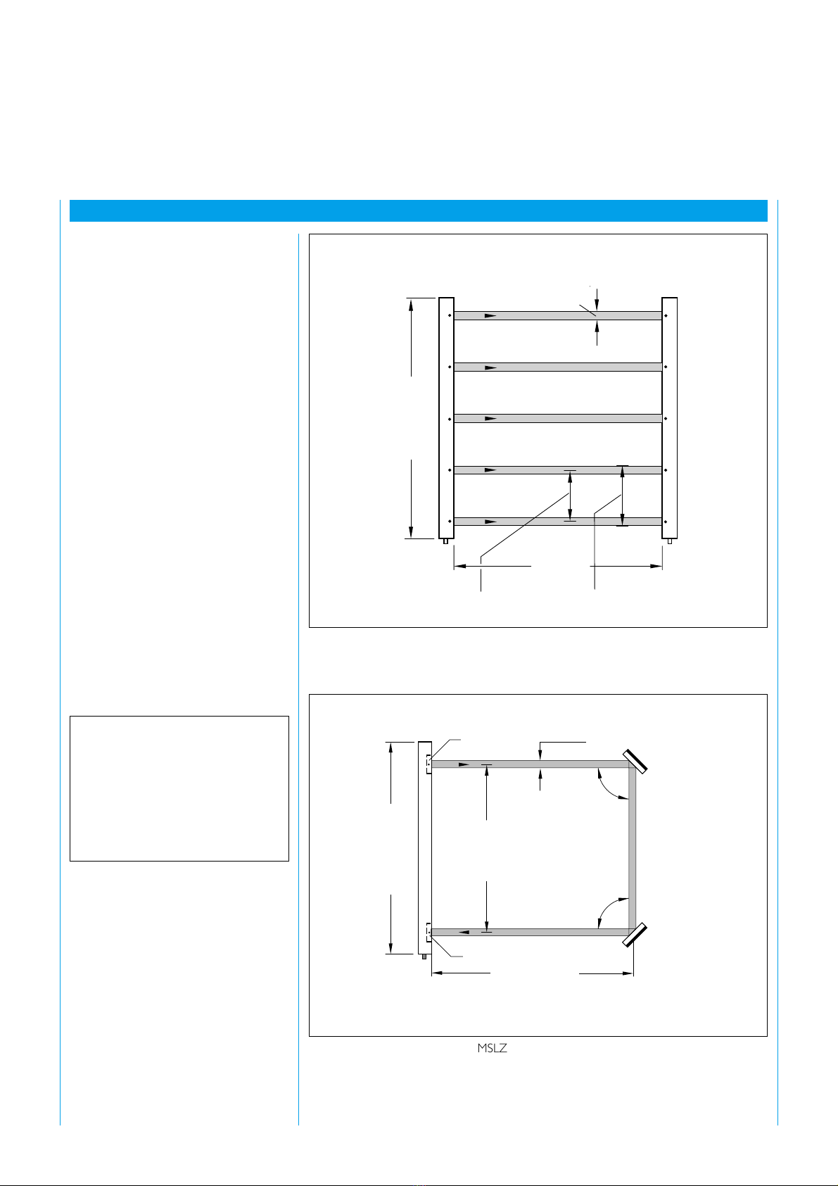
The ac ive side con ains he sender
and receiver elemen s wi h a beam
gap of 500 mm (
fig. 2
). The passive
side is realised wi h corner mirrors.
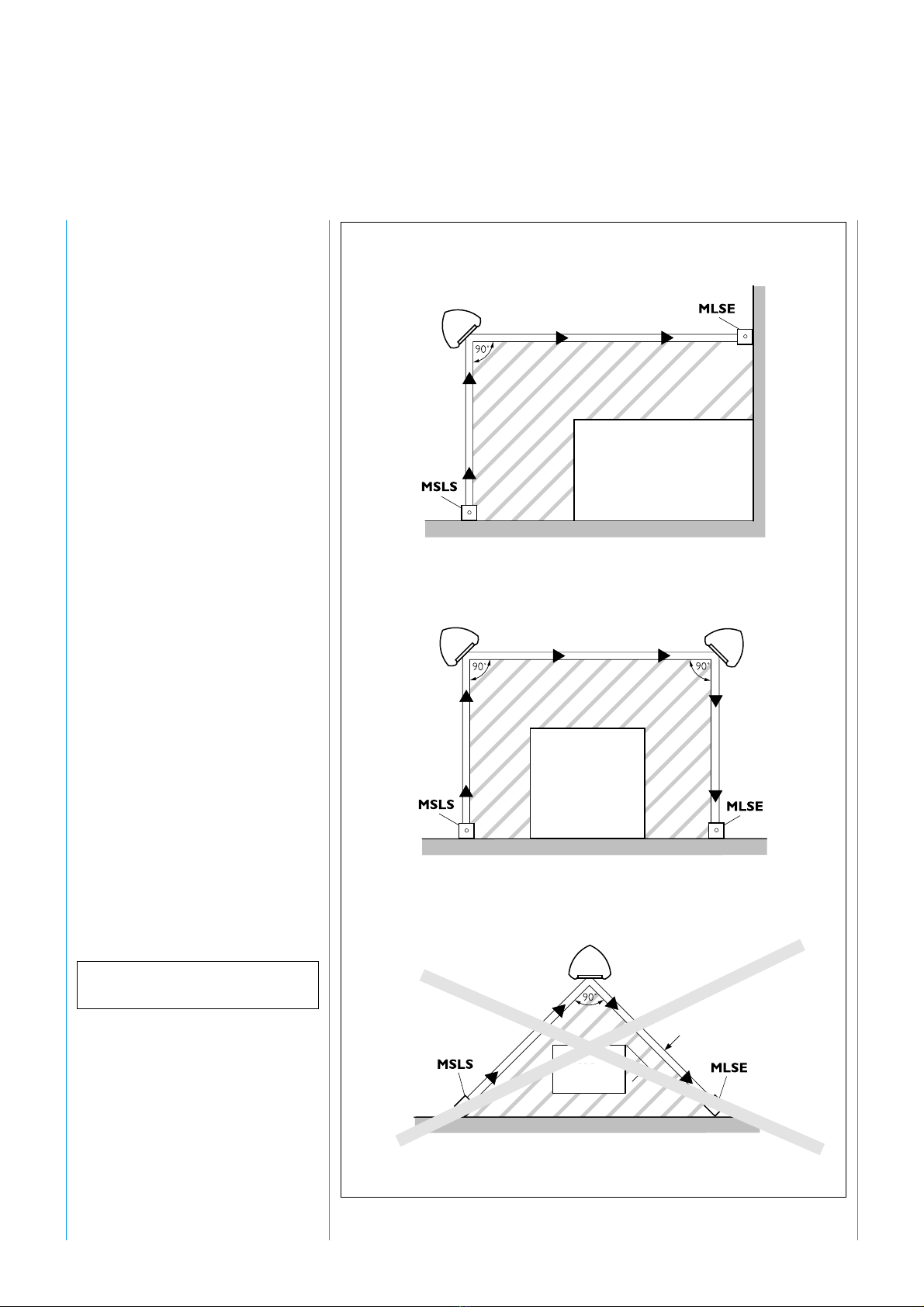
The following key specifica ions are
valid for he MSLZ:
Dis ance:
Ac ive/passive side max. 7.5 m
Beam gap 500 mm