SIC FCC3-48/7 Manuel utilisateur
Montageanweisung
Installation Instructions
Berthold Sichert GmbH
Kitzingstraße 1 - 5 | D -12277 Berlin
www.Sichert.com
AllehierenthaltenenAngabensindnachbestemWissenrichtigundzuverlässig.SiesindjedochkeineEigenschaftszusicherung.DerAnwenderunsererProduktemussineigener
Verantwortung über die Eignung für die vorgesehene Anwendung entscheiden. Unsere Produkthaftung richtet sich ausschließlich nach unseren Verkaufs-, Lieferungs- und
Zahlungsbedingungen. In keinem Fall sind wir haftbar zu machen für irgendwelche zufälligen, indirekten Schäden oder hieraus resultierenden Folgeschäden jeder Art.
All of the above information is believed to be reliable. Users, however, should independently evaluate the suitability of each product for their application. SICHERT
makes no warranties as to the accuracy or completeness of the information, and excludes any liability regarding its use. SICHERT’s only obligations are those in the
Standard Terms and Conditions of Sale, Delivery and Payment and in no case will SICHERT be liable for any incidental, indirect, or consequential damages arising therefrom.
Telefon | Phone: +49 30 74707-0
Telefax | Fax: +49 30 74707-20
Dokument | Document: 59.2519.00.10
Revision | Revision: F
Ersteller | Author: Nee
Fiber Connection Cabinet
FCC3-48/7
FCC3-48/10
FCC3-24/7
FCC3-24/10
Beiliegende Montageanleitungen, Datenblätter und Beiblätter sind zu beachten.Beiliegende Montageanleitungen, Datenblätter und Beiblätter sind zu beachten.
Note also the attached instructions, data sheets and supplementary notes.Note also the attached instructions, data sheets and supplementary notes.

Seite | Page 2von | of 28
Inhaltsverzeichnis Contents Seite | Page
1 Sicherheitsbestimmungen Safety standards 3
2 Lieferumfang Scope of supply 4...5
3 Maße Dimensions 6
4 Schließsystem Locking system 7
5Führung und Bodenmatrix Routing and matrix of base plate 8...9
6 Vorbereitungen Preparations 10
7 Montage Sockel und Gehäuse Installation of plinth and cabinet 11
8 Montage Hauptkabel Installation of the trunk cable 12...15
8.1 Bündeladerkabel Loose tube cable 12...13
8.2 Minikabel mit Rohr Mini cable with duct 14...15
9 Montage Verzweigerkabel Installation of distribution cable 16...17
10 Spleißmodul Fiber tray unit 18...19
11 Kassettensystem Fiber tray system 20...21
12 Demontage Gehäuse und Sockel Disassembly of cabinet and plinth 22...23
13 Reinigung Cleaning 24
14 Bestelldaten Order data 25...27
Demontage- und
Entsorgungshinweis Disassembly and
disposal information 28
Kurzbeschreibung | Key facts and features
Das FCC3 wurde für die Aufstellung im nicht wettergeschützten Bereich (IP 54) konzipiert.
Es dient als Glasfasernetzverteiler in passiven optischen Netzen und ist ausgestattet mit max. 54
Spleißkassetten und einem Rohr-Management für bis zu 50 bzw. 30 Rohre Ø 7 oder Ø 10 mm.
Gehäuse und Sockel bestehen aus glasfaserverstärktem Polycarbonat (PC-GF5 RAL 7038).
The FCC3 is designed to protect and manage ber optic cables for broadband supply in outdoor
applications (IP 54). The cabinet is supplied for max. 54 ber splice trays and a management system
to accomodate up to 50 or 30 Ø 7 or Ø 10 mm blown duct tubes.
Cabinet and plinth are made of glass-reinforced polycarbonate (PC-GF5 RAL 7038).
Zeichenerklärung | Explanation of symbols
Anweisung beachten
Refer to instruction Gebot
Mandatory action Warnung
Warning
12Arbeitsschritte
Working steps AVariante
Version AA11Teil / Montagegruppe
Part / assembly group
Seite | Page 3von | of 28
Unfallverhütungsvorschriften und Sicherheitsregeln (u.a.):
Sicherheitsvorschriften
■Unfallverhütungsvorschrift „Grundsätze der Prävention“ (DGUV V1)
und „Arbeitsschutzverordnung zu künstlicher optischer Strahlung“ (OStrV).
Sicherheitsmaßnahmen
■Unmittelbar nachAbschluss der Montage erfolgt die Überprüfung aller Sicherheitseinrichtungen.
■Bei der Montage aller Zuführungen darf der Betrieb der aufgestellten Einheit nicht behindert
werden. Es dürfen keine Stolperfallen entstehen. Erforderliche Mindestabstände müssen
eingehalten werden.
Jede Person, die mit der Aufstellung, Inbetriebnahme, Bedienung oder Wartung
der Einheit beauftragt ist, muss die Montageanweisung gelesen und verstanden haben.
Safety informationSafety information
The personnel for installation, assembly, operation and maintenance must possess
the appropriate qualication for this type of work. The operational security of product
supplied is only guaranteed when it is used in accordance with the regulations.
Relevant standards and guidelines must be observed!
Jede Person, die mit Einbau, Inbetriebnahme, Bedienung oder Wartung der Einheit
beauftragt ist, muss die entsprechende Qualikation für diese Arbeiten aufweisen.
Die Betriebssicherheit der Anlage ist nur bei bestimmungsgemäßer Anwendung
gewährleistet. Geltende Normen und Richtlinien sind zu beachten!
Accident prevention regulations (among others):
Safety regulations
■Accident prevention regulation „Principles of Prevention“ (DGUV V1)
and „Safety Regulations on Articial Optical Radiation“ (OStrV).
Safety measure
■The inspection of safety devices must be undertaken after completion of the assembly work.
■During the assembly of all feeds the operation of the unit must not be obstructed.
Tripping hazards must be prevented. The minimum clearances have to be met.
This instruction manual contains informations to enable the user to work safely and
correctly. Only when the manual is understood and adhered to can danger be avoided.
1 Sicherheitsbestimmungen Safety standards
Seite | Page 4von | of 28
2 Lieferumfang Scope of supply
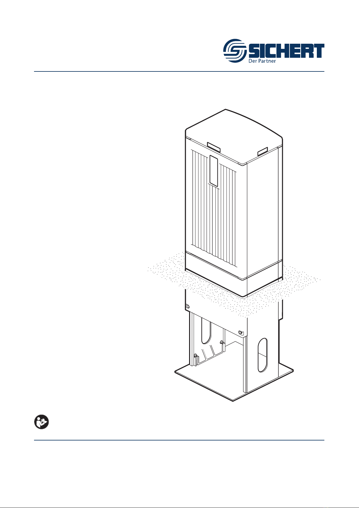
Gehäuse mit Sockel
Cabinet with plinth
Das Gehäuse wird vormontiert (mit Sockel) geliefert. Dem Gehäuse liegen Beipacks für den
Glasfaser-Einbausatz bei. Schlüssel und DIN Prolhalbzylinder nicht im Lieferumfang.
The cabinet will be delivered preassembled (with plinth). The cabinet comes with accessory
packs for the ber kit. locks and keys not supplied - standard DIN half prole locks to be used.
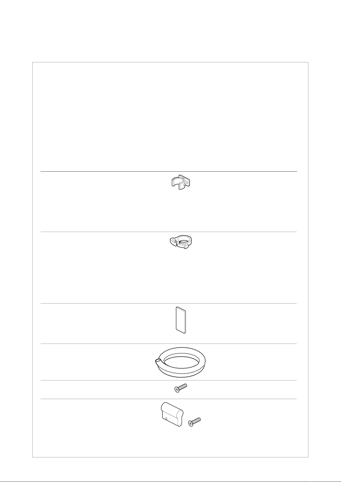
Beipacks
Accessory kit
Teil | Part Anzahl | Quantity
FCC3- 24/7 24/10 48/7 48/10
Clip für Rohr
Clip for duct
Ø 7 mm
Ø 10 mm
Ø 12...14 mm
Ø 16 mm
Ø 20 mm
50
–
6
6
6
–
50
6
6
6
50
–
6
6
6
–
50
6
6
6
Zugabfangung für Rohr
Strain relief element for duct
Ø 7 mm
Ø 10 mm
Ø 12 mm
Ø 14 mm
Ø 16 mm
Ø 20 mm
50
–
6
6
6
6
–
50
6
6
6
6
50
–
6
6
6
6
–
50
6
6
6
6
Abschlussplatte Clipschiene
End plate for clip rail 10 10 10 10
Wellrohr
Flexible conduit 1111
Schraube für Prolhalbzylinder
Screw for lock cylinder 1111
Blindzylinder
(nur bei Doppelschließanlage)
Dummy cylinder
(for double locking only) +
1111
Seite | Page 5von | of 28
Bodenplatte | Base plate
FCC3-48/7:
48x Ø 7 mm +6x Ø 12...20 mm
FCC3-48/10:
48x Ø 10 mm +6x Ø 12...20 mm
FCC3-24/7:
24x Ø 7 mm +6x Ø 12...20 mm
FCC3-24/10:
24x Ø 10 mm +6x Ø 12...20 mm
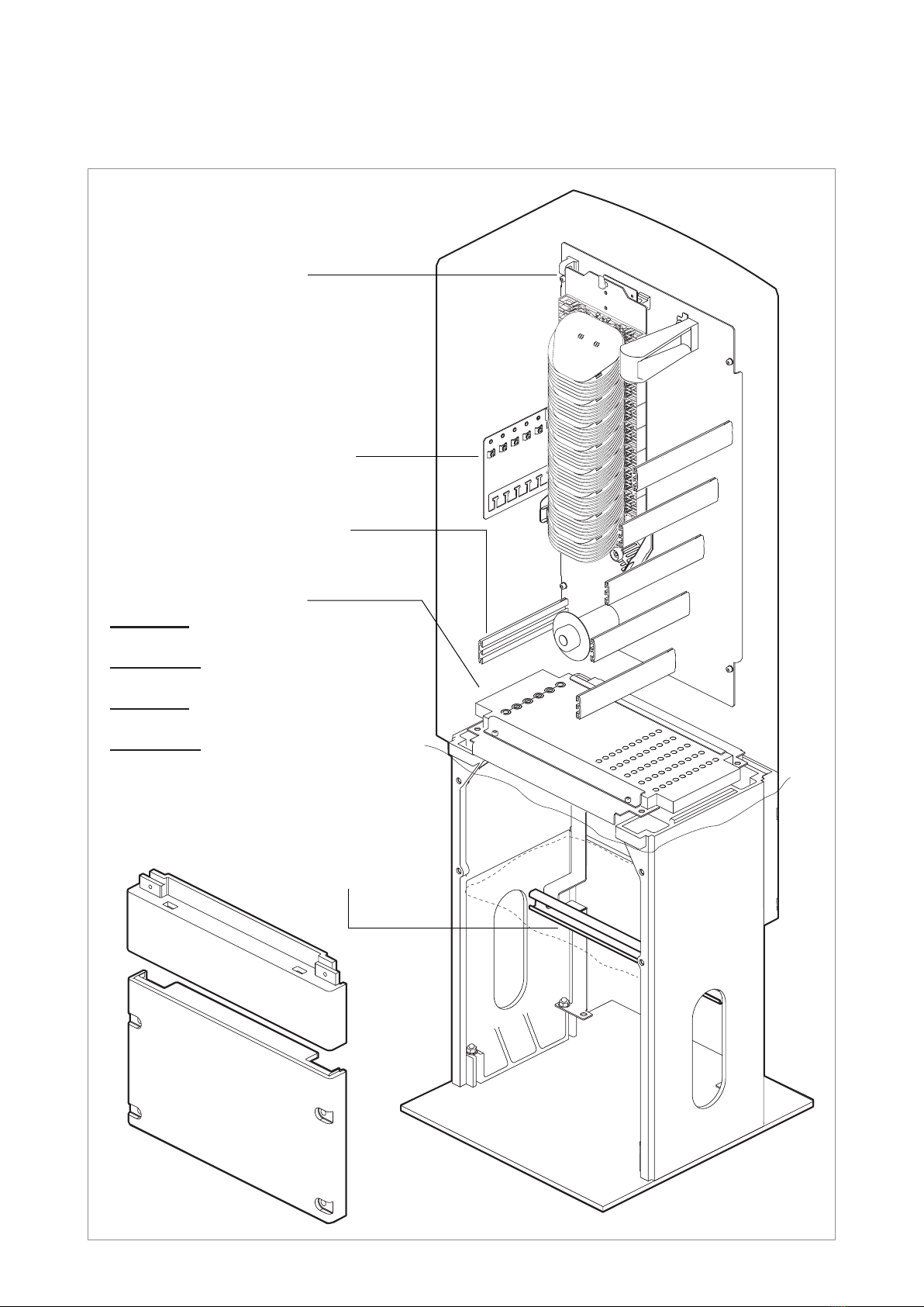
SystemübersichtSystemübersicht (Standard)(Standard)
System overview (standard)
Rohrverband- und
Kabelabfangung
Strain relief for duct
bundles and cables
Rohrabfangung
Clip rails for ducts
Spleißkassettensystem
für max. 54 Rastplätze (SC)
Fiber tray system
for max. 54 tray positions (SC)
Gehäuse
Cabinet
Sockel
Plinth
Kabelabfangung
Strain relief for cables
Seite | Page 6von | of 28
Leergewicht Gehäuse ca. 16 kg
Weight of empty cabinet about 16 kg
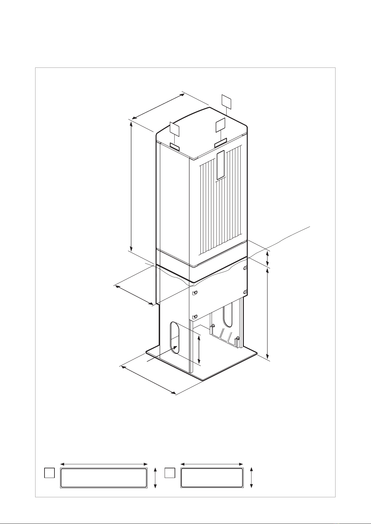
3 Maße Dimensions
Außenmaße (in mm)
Outer dimensions (in mm)
Gewicht
Weight
Kennzeichnungen: Standard [neutral]
Identication plates: [neutral] as standard
69
21
92
21
858
300
425
600
Sockel
Plinth
Gehäuse
Cabinet
Erdgleiche
Ground level
100
A
B
B
200200
444
Ø 70Ø 70
A B
Seite | Page 7von | of 28
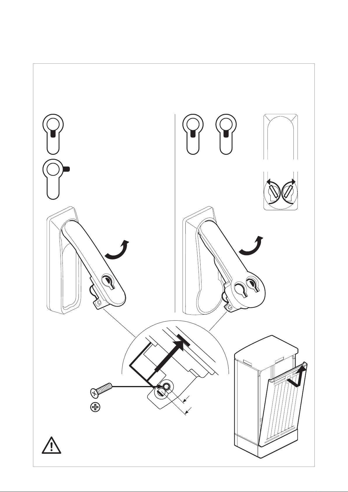
4 Schließsystem Locking system
(Standardschließungen) (Standard locking systems)
Schwenkhebel Doppelschließanlage
Swivel handle double locking mechanism
0° 0°
0°
Schwenkhebel Einfachschließanlage
Swivel handle single locking mechanism
Hinweise des Schließsystemherstellers beachten
Observe locking system manufacturer‘s notes
90° rechts
90° right side
StecktürStecktür
Slot-in doorSlot-in door
ÖffnungsrichtungÖffnungsrichtung
Opening directionOpening direction
(Schwenkhebel Metall)
(Swivel handle made of metal)
(Schwenkhebel Kunststoff)
(Swivel handle made of plastic)
Einstellung Prolhalbzylinder (nach DIN 18252)
Setting of lock cylinder (according to DIN 18252)
Zylinderlänge:
Length of cylinder:
a) 40 mm
b) 45 mm a)
b)
1x1x
Seite | Page 8von | of 28
1
2
3
4
5
6
≥ Ø 10 mm
≥ Ø 16 mm
Loop
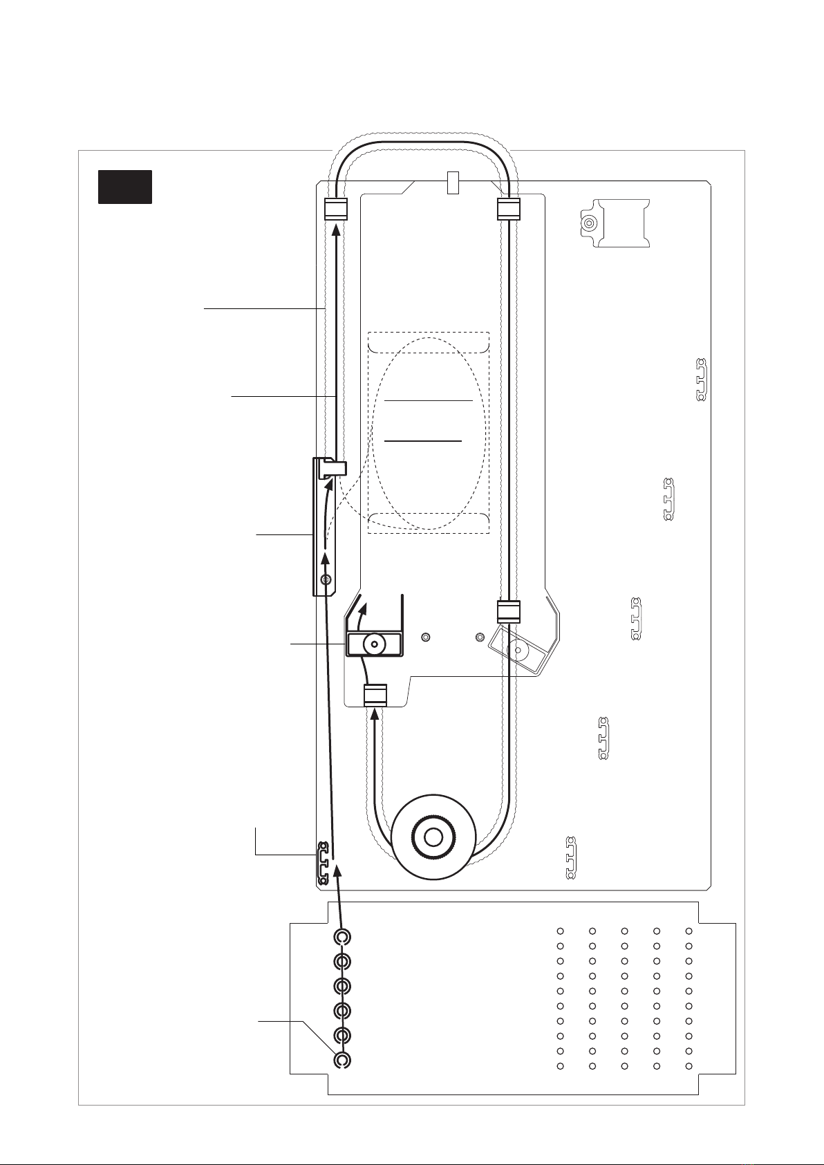
5 Führung und
Bodenmatrix Routing and
matrix of base plate
Bodenmatrix
Matrix of base plate
Bündeladern
Hauptkabel
Loose tubes
of trunk cable
Wellrohr
Flexible conduit
Kabelabfangung
Strain relief for cables
Rohrabfangung
Strain relief for ducts
Abfangung für Bündeladern
Strain relief for loose tubes
IN
Nachrüstsatz:
Bündelablage
Upgrade kit:
Loose tube
slack storage
(Vorschlag)
(Suggestion)
Seite | Page 9von | of 28
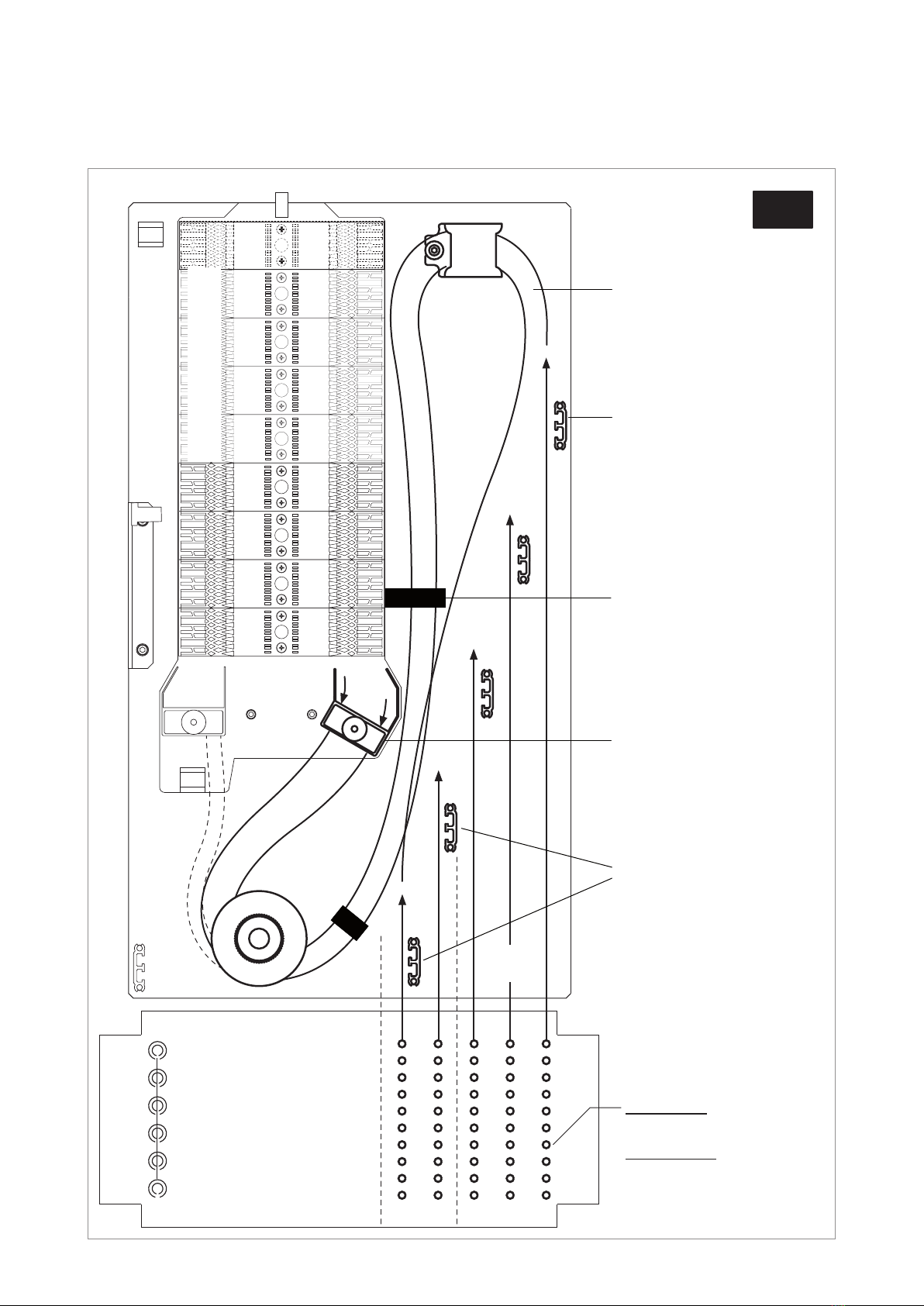
1
10
41
FCC3-xx/7:
≥ Ø 7 mm
FCC3-xx/10:
≥ Ø 10 mm
Bodenmatrix
Matrix of base plate
Rohre
Ducts
Klettband
Hook-and-loop tape
Kabel / Bündeladern
Cables / loose tubes
Rohrabfangung
Strain relief for ducts
Abfangung für Kabel oder
Bündeladern
Strain relief for cables
or loose tubes
1
2
3
4
5
8
7
6
5
4
3
2
1
21
50 30
Nur bei FCC3-48
For FCC3-48 only
+
5...8 zusätzlich bei FCC 48
5...8 additional for FCC 48
FCC3-24FCC3-48
OUT
(Vorschlag)
(Suggestion)
Seite | Page 10 von | of 28
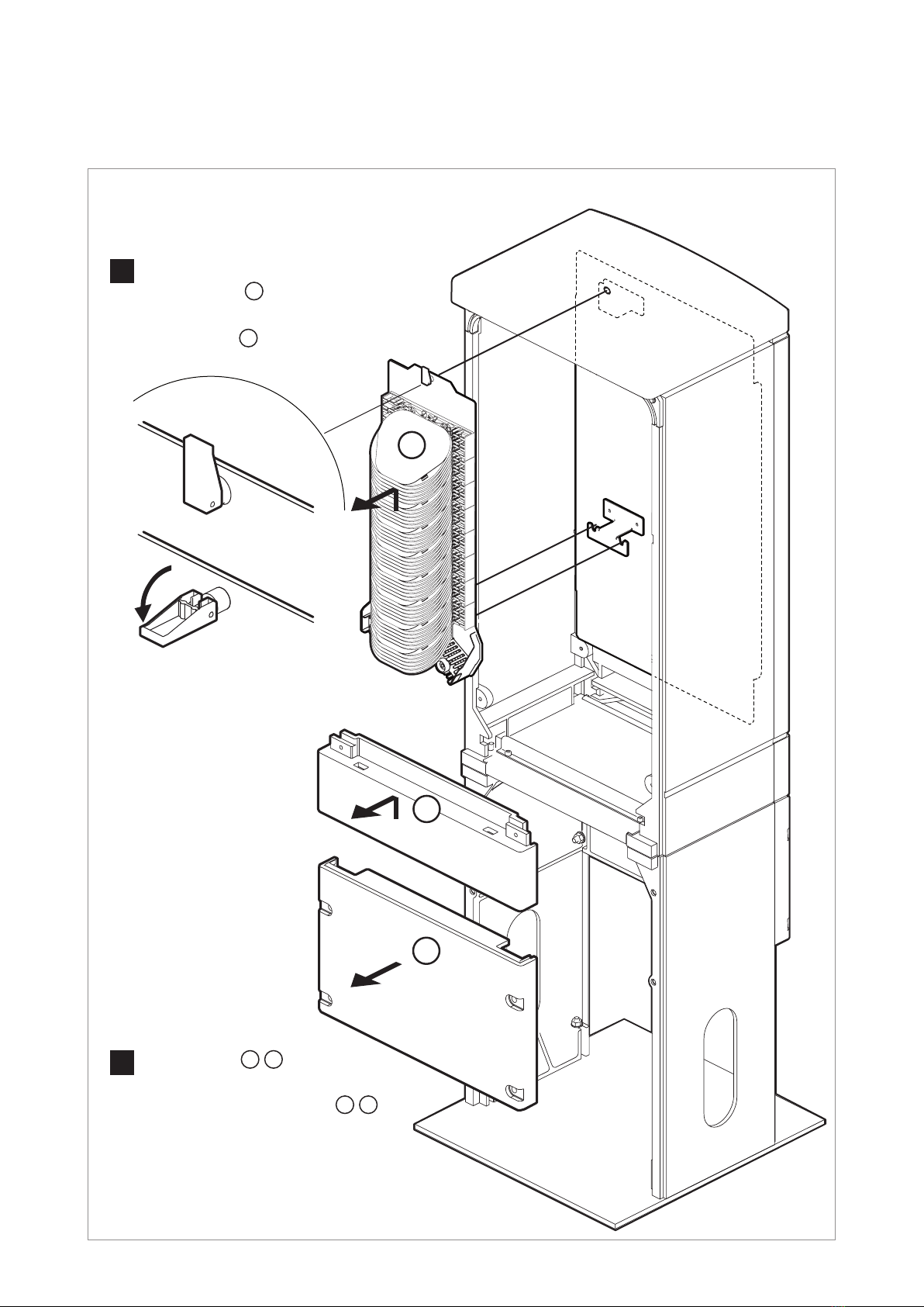
6 Vorbereitungen Preparations
2FrontplattenFrontplatten 2a 2b entfernenentfernen
(Siehe Seite 22 + 23).
Remove the front panels Remove the front panels 2a 2b
(See page 22 + 23).
Gehäuseteile entfernen
Remove components of the cabinet
Gehäuse öffnen undGehäuse öffnen und
SpleißmodulSpleißmodul 1entfernen.entfernen.
Open cabinet and remove Open cabinet and remove
the tray unit the tray unit 1..
2b
2a
1
1
Ce manuel convient aux modèles suivants
3
Table des matières
Manuels Électricité industrielle populaires d'autres marques


Murata
Murata GJM0335C1E4R4BB01 Series Manuel utilisateur

Stahl
Stahl 8575/12 Manuel utilisateur

SI
SI Pegasus Manuel utilisateur

Murata
Murata GRM1555C1H2R7CA01 Seies Manuel utilisateur

Murata
Murata GRM0225C1E6R4BA03 Series Manuel utilisateur

Cooper Power Systems
Cooper Power Systems VXE15 Manuel utilisateur

S&C
S&C Vista SD Manuel utilisateur

Murata
Murata GRM0335C2A7R3CA01 Series Manuel utilisateur

Siemens
Siemens 3VA9988-0BM10 Manuel utilisateur

Siemens
Siemens SITRANS LVS100 Manuel utilisateur

Murata
Murata GRM32ER60G227ME05 Series Manuel utilisateur

Siemens
Siemens SENTRON SUPERSWITCH 3KL82 Series Manuel utilisateur