SIBER PREMIUM DF EVO Manuel utilisateur

Installation Manual
SIBER DF

1 DELIVERY 3
1.1 CONTENTS OF THE DELIVERY 3
1.2 OPTIONAL ACCESSORIES FOR SIBER DF EVO 4
2 APPLICATION 5
3 MODEL 6
3.1 TECHNICAL SPECIFICATIONS 6
3.2. CHARACTERISTIC CURVES 7
3.3 CONNECTIONS AND DIMENSIONS 9
3.4 EXPLODED VIEW OF THE UNIT 10
4 OPERATION 11
4.1 DESCRIPTION 11
4.2 BY-PASS CONDITIONS 11
4.3 ANTI-ICE SECURITY 11
5 INSTALLATION 12
5.1 GENERALALITIES 12
5.2 POSITION OF THE UNIT 12
5.3 CEILING MOUNTING 13
5.4 WALL MOUNTING 15
6 NOZZLE ORIENTATION 17
7 CONNECTION OF THE CONDENSATE DRAIN 19
8 CHANGE OF FILTERS 20
9 ELECTRICAL CONNECTION (Only for the PREMIUM rangeof Siber DF EVO ) 21
9.1 MAINS CONNECTION 21
10 MONITOR YOUR HOME -PROBES / WIRELESS CONTROLS 23
11 SMART CONNECTIVITY 24
11.1 MODBUS - RS485 24
11.2 KNX -EVO CONNECT 24
11.3 BRIDGE ETHERNET -SIBER EVO APP 25
12. MAINTENANCE 26
12.1 FILTER MAINTENANCE (FOR THE USER) 26
12.2 MAINTENANCE OF THE HEAT EXCHANGE (FOR THE INSTALLER) 27
12.3 EXPLODED VIEW AND DESCRIPTION 29
CERTIFICATE OF GUARANTEE 30
SUMMARY

I 3
1 DELIVERY
1.1 CONTENTS OF THE DELIVERY
Before starting the installation of the Dual Flow VMC Unit with Thermal Energy Recovery, you should check whether it has been
delivered complete and intact.
The delivery content of the VMC DF SIBER DF EVO 1/2 unit consists of the following items:
1. VMC DF unit with Thermal Energy Recovery SIBER DF EVO 1/2/ SIBER DF EVO 1/2 Enthalpic
2. Installation Manual
3. Eco design label
4. Installation guides
5. Bag with silentblocks and screws
* If the Unit has been delivered with any visible defects, such as dents or scratches, or if all the items and accessories listed above are
not included, please contact your supplier.
SIBER DF
Unit supplied without regulating control [see section 1.2 for optional accessories]
The use of this Unit is not authorised for persons, including minors, with reduced intellectual capacities, limited physical
capacities, or lack of experience and necessary knowledge, unless they are under the supervision of, or have been
instructed by a person responsible for their safety, in the use of the Unit.
In any case, children should be monitored to ensure that they do not play with the Unit.

I 4
SIBER DF / INSTALLATION MANUAL
DESCRIPTION IMAGE CODE
G4 FILTER COARSE 65% DFFG4
F7 FILTER ePM1 55% DFFF7
G4 + F7 FILTER COARSE 65% - ePM1 55% DFFG4F7
CARBON FILTER DFFCA
F9 FILTER ePM1 80% DFFF9
G4 + F9 FILTER COARSE 65% - ePM1 80% DFFG4F9
Wireless 4-position pushbutton control DFPULS4B
Wireless smart multi-control DFEVOCTRL
Wireless smart humidity sensor DFEVOHR
Wireless smart CO2 sensor DFEVOCO2
RF -Ethernet communication gateway DFEVORFETH
RF -RS485 Communication Gateway DFEVORFRS485
Connect Modbus master KNX converter DFEVOCONNECT
Siber EVO APP
Smart monitoring of equipment and indoor air
quality
Connectivity via
Ethernet gateway
(DFEVORFETH)
1.2 OPTIONAL ACCESSORIES FOR SIBER DF EVO

I 5
2 APPLICATION
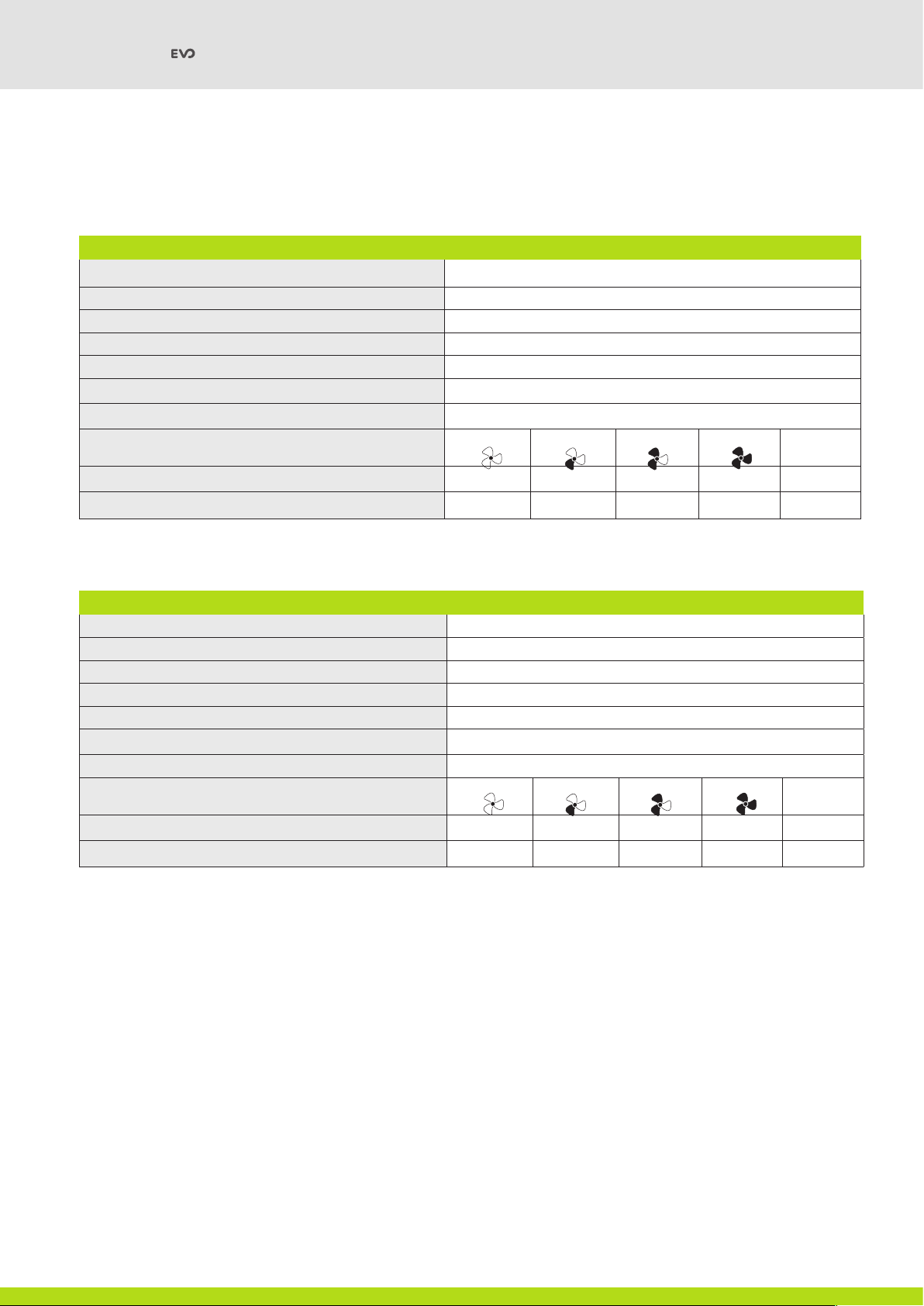
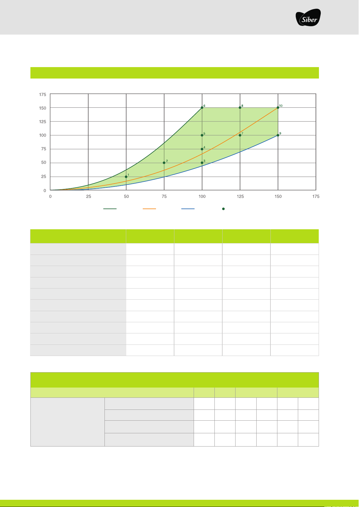
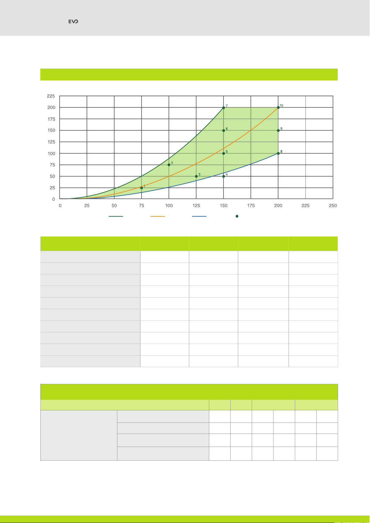
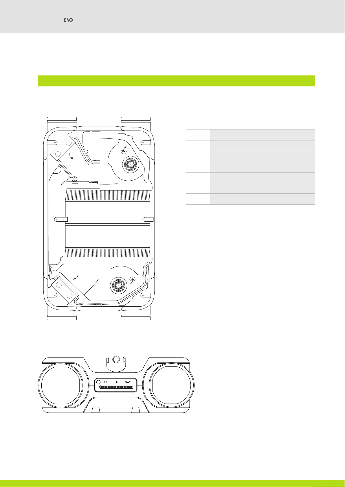
The SIBER DF EVO 1/2 is a Double Flow Controlled Mechanical Ventilation Unit with a Thermal Energy Recovery Unit with an efficiency
of up to 95%, a maximum ventilation capacity of 150 m3/h for the SIBER DF EVO 1 and a maximum capacity of 200 m3/h for the SIBER DF
EVO 2; with low energy consumption fans for both units.
Characteristics of the SIBER DF EVO 1/2 unit:
• Continuous regulation of air flows by means of the control panel.
• Presence of a filter status indicator on the Unit and the possibility of filter status indication on the position selector.
• New smart anti-icing regulation ensures that the unit continues to operate optimally even at low temperatures. If necessary,
switch on the pre-heating battery(optional accessory).
• Low noise level.
• Equipped as standard with a by-pass valve with automatic operation.
• Constant flow regulation.
• Energy saving.
• High Performance.
The SIBER DF EVO 1/2 is available in 2 versions:
• SIBER DF EVO 1/2
• SIBER DF EVO 1/2 Enthalpic
These installation instructions apply to both the SIBER DF EVO 1/2 and the SIBER DF EVO 1/2 Enthalpic.
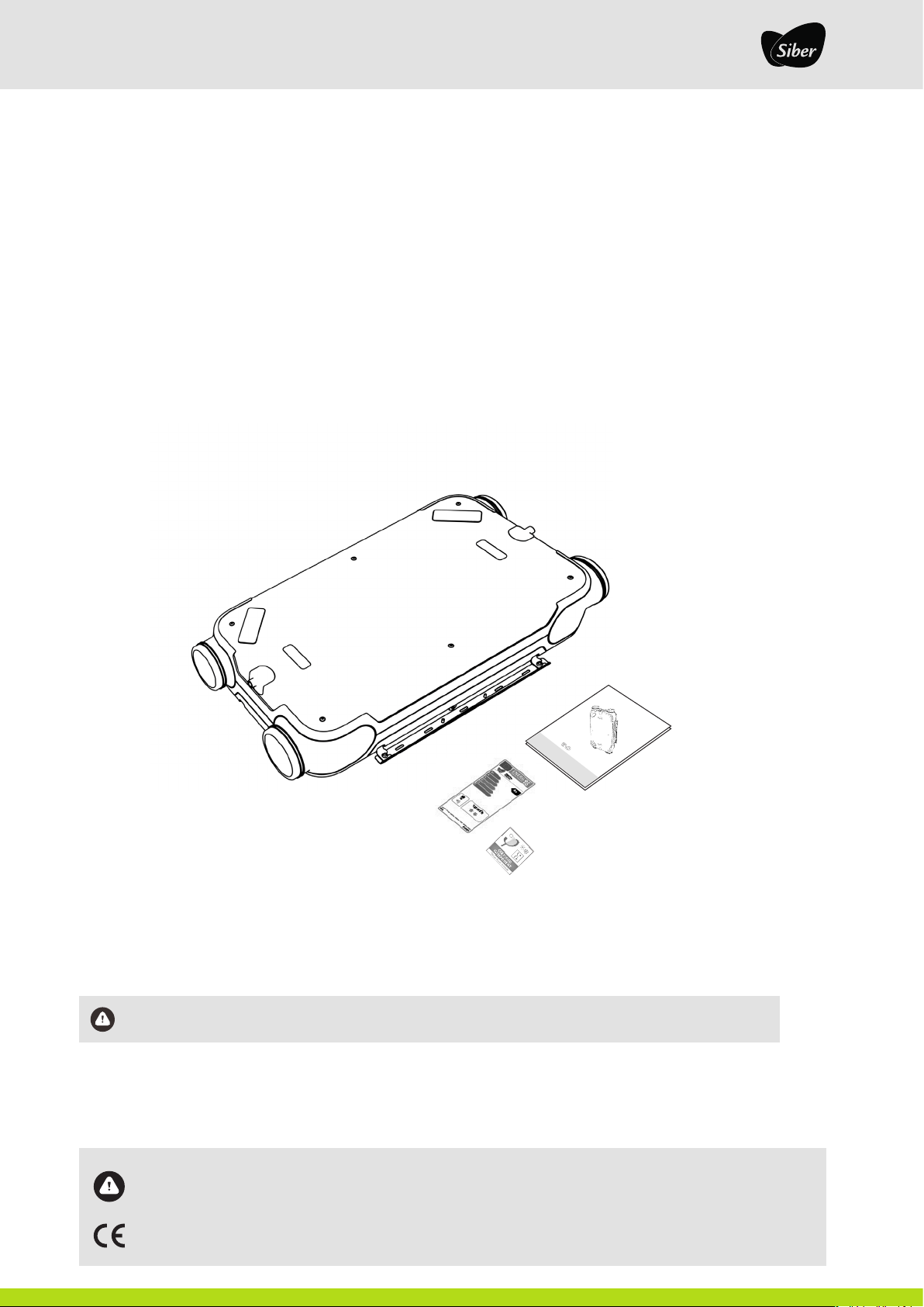
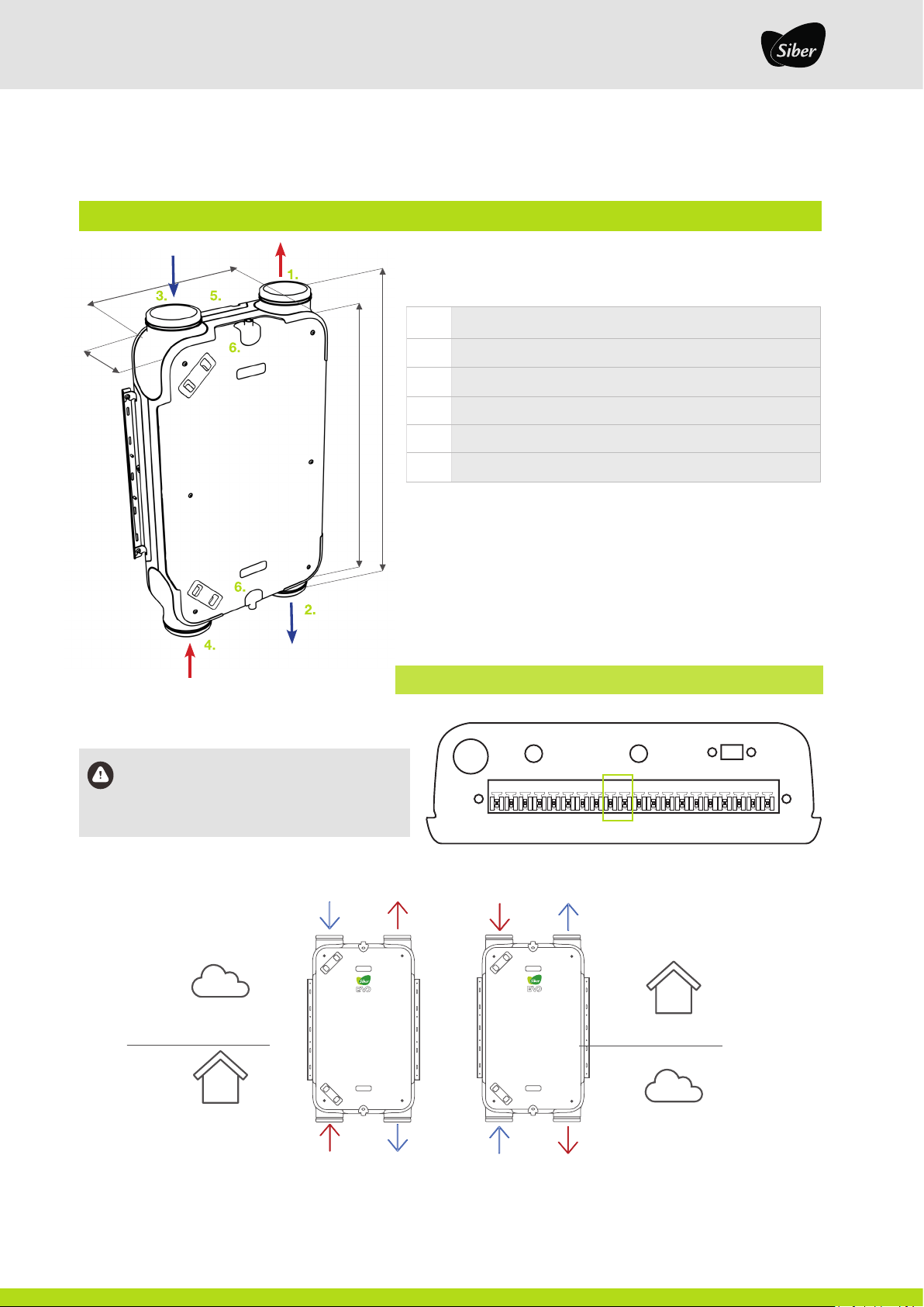
The SIBER DF EVO 1/2 can be wall or ceiling mounted, with the standard fixing brackets included. For the correct position of the duct
connections and their dimensions [see section 3.3].
The factory unit will come with the right-hand version, which can be changed in one simple step [see section 3.3].
Important! For the correct efficiency of the ventilation system, it is recommended not to disconnect the unit,
except for maintenance

I 6
SIBER DF / INSTALLATION MANUAL
3 MODEL
3.1 TECHNICAL SPECIFICATIONS
SIBER DF EVO 1 & DF EVO 1 Enthalpic
Mains voltage 230 V/ 50 Hz
Degree of protection IP 40
Dimensions (l x h x d) 1000 x 600 x 210 mm
Connection diameter 160 Ø
Condensate drain diameter 1/2"
Weight 24 Kg
Filter class Coarse 65% (G4)
Fan position (standard) Boost
mode
Wireless Smart Multi-Controller (optional) 0 1 2 3 Maximum
Ventilation flow rate (m3/h) 30 75 100 140 150
SIBER DF EVO 2 & DF EVO 2 Enthalpic
Mains voltage 230 V/ 50 Hz
Degree of protection IP 40
Dimensions (l x h x d) 1000 x 600 x 210 mm
Connection diameter 160 Ø
Condensate drain diameter 1/2"
Weight 24 Kg
Filter class Coarse 65% (G4)
Fan position (standard) Boost
mode
Wireless Smart Multi-Controller (optional) 0 1 2 3 Maximum
Ventilation flow rate (m3/h) 30 75 100 150 200

I 7
3.2. CHARACTERISTIC CURVES
SIBER®DF EVO 1 & DF EVO 1 Enthalpic
Pressure (Pa)
Flow rate (m3/h)
Working points FLOW (m3/h) PRESSURE (Pa) POWER (W) SFP (W/l/s)
150 25 9.24 0.67
275 50 15.37 0.74
3100 50 20.55 0.74
4100 75 24.52 0.88
5100 100 28.87 1.04
6100 150 37.62 1.35
7125 100 37.13 1.07
8125 150 46.07 1.33
9150 100 48.14 1.16
10 150 150 58.25 1.40
Sound level SIBER®DF EVO 1 & DF EVO 1 Enthalpic
Ventilation flow rate (m3/h) 50 75 100 150
Sound level Lw (A)
Static pressure (Pa) 25 50 50 100 100 150
Box irradiation (dB(A)) 24 34 38 44 45 49
Extraction duct (dB(A)) 28 30 39 42 46 47
Insufflation duct (dB(A)) 42 50 53 56 61 64
dP Low dP Media dP High Working points

I 8
SIBER DF / INSTALLATION MANUAL
SIBER®DF EVO 2 & DF EVO 2 Enthalpic
Pressure (Pa)
Flow rate (m3/h)
Working points FLOW (m3/h) PRESSURE (Pa) POWER (W) SFP (W/l/s)
175 25 12.61 0.61
2100 75 25.31 0.91
3125 50 29.16 0.84
4150 50 39.20 0.94
5150 100 49.65 1.19
6150 150 60.92 1.46
7150 200 72.60 1.74
8200 100 81.33 1.46
9200 150 93.10 1.68
10 200 200 106.48 1.92
Sound level SIBER®DF EVO 2 & DF EVO 2 Enthalpic
Ventilation flow rate (m3/h) 75 125 150 200
Sound level Lw (A)
Static pressure (Pa) 25 50 50 100 150 200
Box irradiation (dB(A)) 33 42 44 46 51 56
Extraction duct (dB(A)) 34 43 45 48 50 57
Insufflation duct (dB(A)) 46 51 59 62 65 66
dP Low Working pointsdP Media dP High

I 9
SIBER DF EVO
3.3 CONNECTIONS AND DIMENSIONS
210 mm
600 mm
1100 mm
1000 mm
Important! To change the factory position (right),
simply jumper wire pins 9 - 10 and you will enter
the left-hand version
1 2 3 4 5 6 7 8 9 10 11 12 13 14 15 16 17 18 19 20
LEGEND STANDARD VERSION
1Exhaust air
2Fresh air supply to the dwelling
3Fresh air intake from outside
4Extraction of stale air from inside the dwelling
5Electrical connection
6Condensate drain connection
*Airflow model right-hand version
MIRROR MODE VERSATILITY
Fresh air
intake from
outdoors
Expulsion of
stale air to
outdoors
Air extraction from
bathrooms and
kitchen
Air supply to
the rooms
Fresh air
intake from
outdoors
Expulsion of
stale air to
outdoors
Air extraction
from bathrooms
and kitchen
Air supply to
the rooms
right
(Factory version)
left
(Mirrored mode)
inside outside
outside inside

I 10
SIBER DF / INSTALLATION MANUAL
3.4 EXPLODED VIEW OF THE UNIT
SIBER DF EVO
1.
1.
2.
3.
3.
4.
5.
3.
6.
7.
3.
2.
LEGEND
1High performance filters
2Energy-efficient engines
3Temperature probes
4High-performance heat exchanger
5100% automatic bypass
6Swivelling condensate drain
7Electrical connections
Table des matières


