SI 7 SERIES Manuel utilisateur

7SERIES
MOTORIZED EXTERNAL

7 Series Motorized External Instructions 2
www.screeninnovations.com Installation Questions: 512-832-6939 BDMEX V2.0 D
1) Do not change the upper limit. Screen damage and injury
may result from improper upper limit setting.
2) The required Operating Temperature Range of this product is
65F - 85F (15C - 29C).
3) Due to the effects of thermal expansion, this screen must be
protected from exposure to direct sunlight.
Warnings

7 Series Motorized External Instructions 3
www.screeninnovations.com Installation Questions: 512-832-6939 BDMEX V2.0 D
Wall Switch /
Limit Setting Tool
Power Cord
Bracket Lock
Nuts
Low Voltage
Trigger Jacks (2)
Mounting Bracket
Screws & Driver Bit
IR Remote & Receiving Eye
Wing End Cap Screws
& Allen Wrench
Wall Switch
Cable (8’ Length)
Unpack the box
Mounting Brackets
Installation Parts List

7 Series Motorized External Instructions 4
www.screeninnovations.com Installation Questions: 512-832-6939 BDMEX V2.0 D
Installing the brackets
1. Determine the mounting position of the brackets on the wall. Provide at least 1/2’’ clearance between top of bracket
and ceiling to allow for fascia clearance. Make sure the brackets are securely mounted to structural lumber 2’’ to 12’’ from
each end of the case. Each bracket must be able to support 200lbs.
2. If mounting to the ceiling use washers to provide 1/2’’ clearance between top of bracket and ceiling. Use a torpedo
level to establish that the brackets are level and plumb. (See illustrations below.) Screw the mounting brackets into the
wall or ceiling using the provided #2 Robertson square driver bit and Deck Mate screws.

7 Series Motorized External Instructions 5
www.screeninnovations.com Installation Questions: 512-832-6939 BDMEX V2.0 D
Hanging the cassette—two installers and two ladders are required to safely lift the cas-
sette into position.
3. Center the cassette under the brackets with the cas-
sette opening on the floor and the curved section facing
away from the wall.
Important Note: Before installing brackets, be certain
the structural components where the brackets are
attached will enable each bracket to support 200 lbs.
All three bracket hooks must be
engaged within the cassette chan-
nels.
4. With two installers and two ladders, lift the cassette up onto the
hooks on both wall brackets. Make certain all 3 bracket hooks are
securely engaged into the channels on the cassette. (See drawing
below.)
5. Verify that the cassette is centered in the viewing area. If
not, move it left or right to align.
6. Slide the machine screws in the top of the cassette
with the center slot of each bracket. See first drawing
on right.
7. Using a Phillips screwdriver, tighten the screw at the
bottom of each bracket until snug. Make sure the
machine screws at the top stay aligned with the
bracket slots so that they do not prevent the case from
moving up into the top surface of the bracket. See
drawing 2 on the right.
8. With a torpedo level on the top or front of the case,
install and tighten the provided lock nuts onto each of
the two machine screws until the case is plumb. (See
drawing 3 on the right.)
132

7 Series Motorized External Instructions 6
www.screeninnovations.com Installation Questions: 512-832-6939 BDMEX V2.0 D
10. a) IMPORTANT: The wing
and tube are going to be lifted
up off the floor-make sure the
wing and tube are centered
and nothing is interfering with
the cables before raising the
screen.
10. b) With one on person on
each side, guide the cables
into the first groove of the
helixes, and apply downward tension to straighten each cable to plumb.
10. c) Using the wall switch, press and hold the Up arrow button until the screen is lifted off the floor, then release the
button to stop the screen.
10. d) Once the screen has been lifted off the floor by the cables, verify that the cables start in the first groove, and are
following the grooves of the helix as shown in the above right image. If you experience a problem with the cables, lower
the screen with the Down button, realign the cables with the grooves, and repeat step 11.c).
Guide cable into
first groove of helix.
Pull straight down on
cables until screen is
raised off the floor.
Raising the screen using the wall switch
Connecting the screen assembly to upper cassette
9. a) Position the black screen packing tube on the floor centered
directly below the case. The “Left” label will be on the viewers left
hand side, while the Front label should be visible on viewer’s right
side.
9. b) Connect the wall switch by first plugging the RJ45 end of the
wall switch cable into any of the RJ45 ports on the left side of the
case. Next, plug other end of the cable (RJ9) into the port on back of
Somfy wall switch-make sure to press in until it clicks.
9. c) Plug in the supplied power cord to power the screen.
9. d) At each end of the black screen tube, locate and unwrap the
left and right steel cables—they are wrapped in grey foam packaging
material. Connect the steel cables to the threaded helixes (inside the
case) by first sliding the cable underneath the edge of the helix as
shown below. Pull down on the cable to lock it in place. Refer to the
three drawings below for guidance.
Make sure cable follows
first groove in helix

7 Series Motorized External Instructions 7
www.screeninnovations.com Installation Questions: 512-832-6939 BDMEX V2.0 D
12. Locate the wing end caps inside the
cassette and pull each down to the end
of the wing as shown in the drawings
below.
11. a) Raise the screen to the desired
viewing height. Start by turning on the
projector and projecting the image at
the desired height on the wall.
11. b) Using the wall switch, press
and hold the Up arrow button to raise
the screen. Release the button when
the top of the projected image is
roughly aligned within corner lines on
both sides of the tube. Fine tune the
screen height by pressing the Up and
Down arrow buttons as necessary.
13. Align pins with holes in wing and secure with black hex screw.
Setting the viewing height and installing the wing end caps
7 Series Motorized External Instructions 8
www.screeninnovations.com Installation Questions: 512-832-6939 BDMEX V2.0 D
Locking the final height of screen
IMPORTANT NOTE: The following steps will permanently lock the final viewing height in
place. Do not proceed with these steps until you’re certain of the final viewing height, and
that the screen is set to that position as described in Step 11.
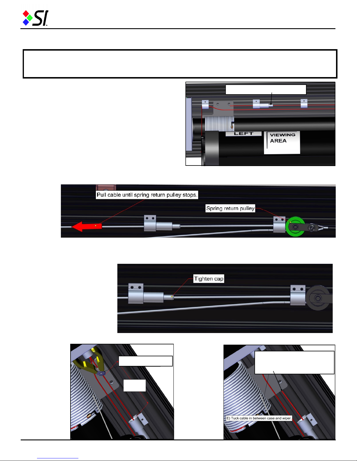
To permanently set drop, perform these steps on each side of
cassette:
14. a) Unlock the grip lock by unscrewing the cap where
the cable passes through—this will allow the cable to be
shortened to the proper length. See drawing on the right.
14. b) Pull cable through the grip lock toward the end of the cassette until the spring return pulley can’t go any further—
this will take slack out of the cable and set the height of the wing. See drawing on the below.
14. c) Turn grip lock cap clockwise to lock the cable in place. See drawing below.
Unscrew grip lock cap here.
14. d) Cut ex-
cess cable be-
tween 5”-6” from
end of grip lock
as shown in the
drawing on the
right. Be certain
to cut the proper
end of the ca-
ble—it should be
the tag end that’s
hanging down
below the cas-
sette opening.
5”- 6”
Cut Excess Cable After cutting to 5” - 6”, tuck
remaining cable under
plastic plate.
14. e) Tuck
leftover cable
under plastic
plate as
shown in the
drawing to the
right. Discard
the excess
cable that
you’ve cut.
7 Series Motorized External Instructions 9
www.screeninnovations.com Installation Questions: 512-832-6939 BDMEX V2.0 D
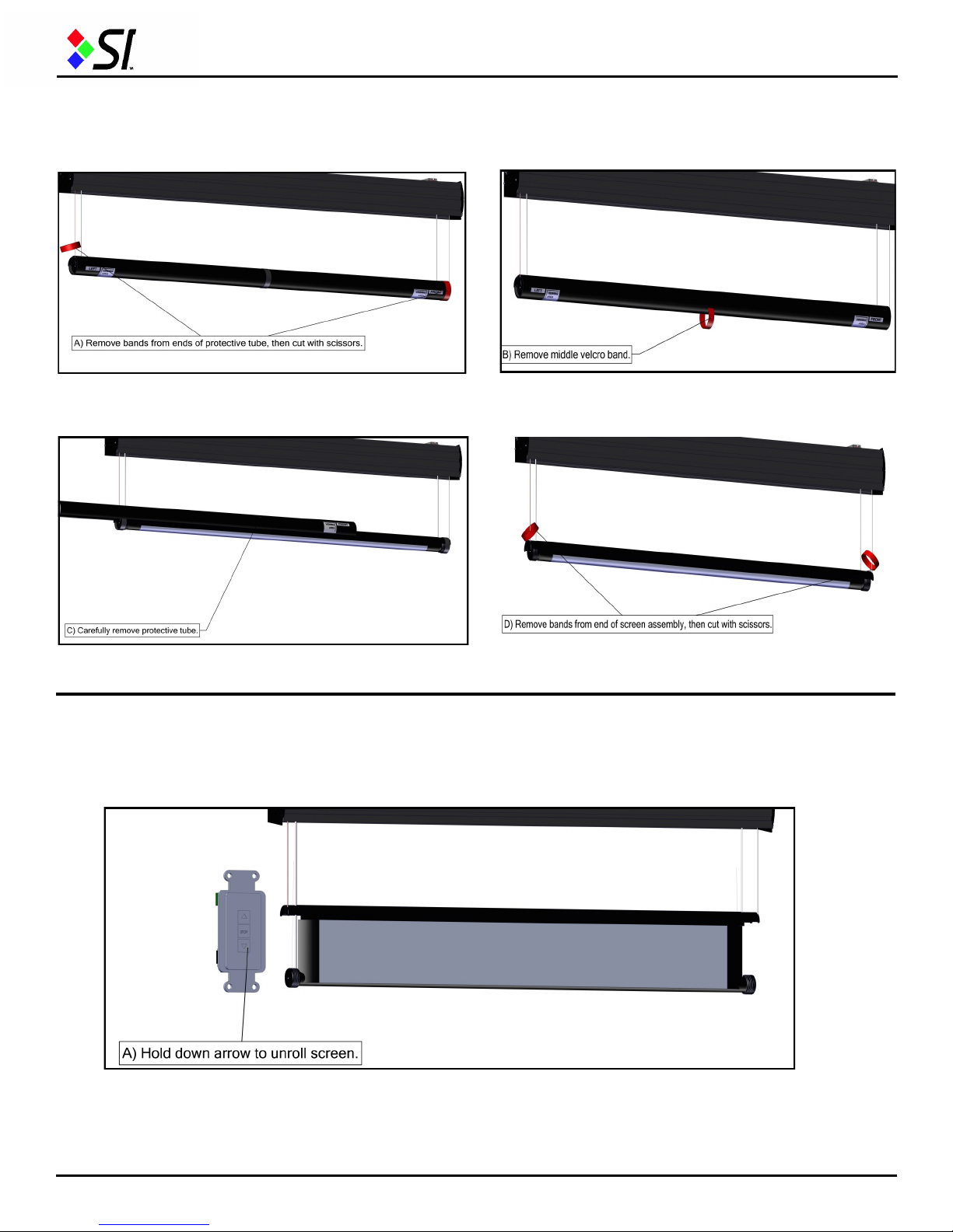
15. b) Remove Velcro band from middle of tube and discard.
15. d) Remove rubber bands off tube on each end, then
cut with scissors and discard.
15. c) Carefully remove protective tube from screen assembly.
Setting the lower screen limit
16. Using the wall switch, press and hold the Down arrow and the screen will begin to open (continued on next page).
Removing protective tube from screen
15. a) Slide rubber bands off tube on each end, then cut
with scissors and discard.

7 Series Motorized External Instructions 10
www.screeninnovations.com Installation Questions: 512-832-6939 BDMEX V2.0 D
Setting the lower screen limit
16. a) Continue unrolling the screen with the Down button while carefully watching the bottom tube from behind the
screen. Release the button when the arrow on the tube is at 12:00—denoted by a red arrow on the tube (as shown in the
images below). You may toggle with the Up and Down arrows to fine tune the 12:00 position of the arrow.
16. b) Turn the wall switch over, and move the slide switch from the lower position to the middle position as shown in the
below right image. Do not proceed until the slide switch is in the middle position. The upper and lower limits of the motor
are now set and the screen is ready for operation.
17. To attach fascia, lift it over the top edge of the cassette and insert the tab on the fascia into the slot in the top front of
cassette. (See illustrations below.)
Attaching the fascia
Insert tab into slot
Finished fascia appearance
Press the bottom of the fascia to secure it
against the case on both sides of the cassette.
Table des matières
Autres manuels SI Accessoires


