Showline SL ParBlazer 100 UV Mode d’emploi

SL ParBlazer 100 UV
SL ParBlazer 100 UV Installation & User’s Manual
Version as of: 17th Sep, 2015 Rev1.0
2015 Philips Group. All rights reserved.
Showline Offices
Showline - Dallas
10911 Petal Street
Dallas, TX 75238
Tel: 214-647-7880
Fax: 214-647-8030
Showline - Europe
Marssteden 152
Enschede 7547 TD
The Netherlands
Tel: +31 53 4500424
Fax: +31 53 4500425
Showline - Auckland
19-21 Kawana Street
Northcote, Auckland 0627
New Zealand U.S.A
Tel: +64 9 481 0100
Fax: +64 9 481 0101
Showline - Asia
Unit C, 14/F, Roxy Industrial Centre
No. 41-49 Kwai Cheong Road
Kwai Chung, N.T., Hong Kong
Tel: +852 2796 9786
Fax: +852 2798 6545
Website:
www.philips.com/showline
The material in this manual is for information purposes only and is subject to change without notice. Showline assumes
no responsiblitity for any errors or omissions which may appear in this manual. For comments and suggestions regarding
corrections and/or updates to this manual, please visit the Showline website at or contact yourwww.philips.com/showline
nearest Showline office.
Note: Information contained in this document may not be duplicated in full or in part by any person without prior written
approval of Showline. Its sole purpose is to provide the user with conceptual information on the equipment mentioned. The use of
this document for all other purposes is specifically prohibited.
Document Number: SL ParBlazer 100 UV User’s Manual

Additional Resources for DMX512
For more information on installing DMX512 control systems, the following publication is available for purchase
from the United States Institute for Theatre Technology (USITT), "Recommended Practice for DMX512: A Guide
for Users and Installers, 2nd edition" (ISBN: 9780955703522). USITT Contact Information:
USITT
315 South Crouse Avenue, Suite 200
Syracuse, NY 13210-1844
Phone: 1.800.938.7488 or 1.315.463.6463
www.usitt.org
Showline Limited Two-Year Warranty
Showline offers a two-year limited warranty of its luminaires against defects in materials or workmanship from the
date of delivery. A copy of the Showline two-year limited warranty containing specific terms and conditions can be
obtained by contacting your local Showline office.
Warnings and Notices
When using electrical equipment, basic safety precautions should always be followed including the following:
READ AND FOLLOW ALL SAFETY INSTRUCTIONS.
Do not mount near gas or electric heaters.
Equipment should be mounted in locations and at heights where it will not readily be subject
to tampering by unauthorized personnel.
The use of accessory equipment not recommended by the manufacturer may cause an unsafe
condition.
Do not use this equipment for other than intended use.
Refer service to qualified personnel.
WARNING: You must have access to a mains circuit breaker or other power disconnect device
before installing any wiring. BE sure that power is disconnected by removing fuses or turning the
mains circuit breaker off before installation. Installing the device with power on may expose you
to dangerous voltages and damage the device. A qualified electrician must perform this installation.
WARNING: Refer to National Electrical Code and local codes for cable specifications.
Failure to use proper cable can result in damage to equipment or danger to personnel.
WARNING: This equipment is intended for installation in accordance with the Nation Electric
Code and local regulations. It is also intended for installation in indoor applications only. Before
any electrical work is performed, disconnect power at the circuit breaker or remove the fuse to
avoid shock or damage to the control. It is recommended that a qualified electrician perform this
installation.
Installation & User’s ManualSL ParBlazer 100 UV
IMPORTANT INOFRMATION

TABLE OF CONTENTS
Showline Offices Inside Front Cover
IMPORTANT INFORMATION
Warnings and Notices
Additional Resources for DMX512
Showline Limited Two-Year Warranty
TABLE OF CONTENTS
PREFACE
About this Manual
Included Items
SL ParBlazer 100 UV OVERVIEW
SL ParBlazer 100 UV Components
INSTALLATION AND SET UP
Connecting Power
Connecting SL ParBlazer 100 UV to AC Power
Truss / Hanging Applications
Floor Mounting
Connecting to the DMX512 Network
Mounting Luminaire
OPERATION AND PROGRAMMING
LCD Display and Menu System
LCD Display and Menu System Operation
SL ParBlazer 100 UV Menu Tree
Master / Slave Operational Mode
Dimming Curve Selection
DMX CONTROL
RDM PARAMETER IDs
8-Bit Mode
16-Bit Mode
SL ParBlazer 100 UV DMX Mapping
SL ParBlazer 100 UV RDM Parameter IDs
CLEANING AND CARE
Special Cleaning and Care Instructions
Front Lens Cleaning
Service and Maintenance
TECHNICAL SPECIFICATIONS
Operational Specifications
Luminaire Dimensions
Table of contents
2
1
1
1
3
3
4
5
5
8
8
7
8
9
10
11
12
13
14
14
14
15
18
18
18
19
20
PREFACE
1. About this Manual
The document provides installation and operation instructions for the following products:
Please read all instructions before installing or using this product. Retain this manual for future reference.
Additional product information and descriptions may be found on the product specification sheet.
Note: The SL ParBlazer 100 UV luminaire works from 100 to 240 VAC (auto-ranging).
2. Included Items
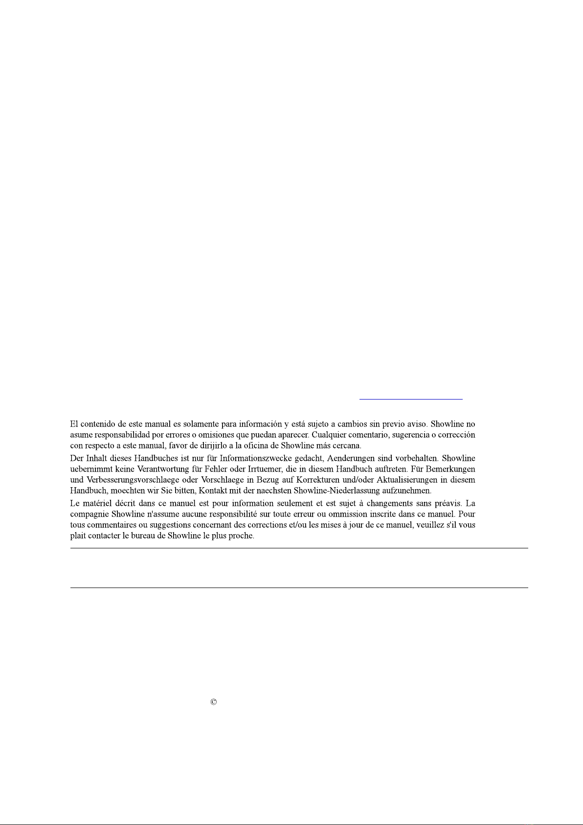
Each SL ParBlazer 100 UV luminaire includes the following items:
SL ParBlazer 100 UV Luminaire
SL ParBlazer 100 UV Luminaire
Quick Start Guide
3
About this Manual
Installation & User’s ManualSL ParBlazer 100 UV
SL ParBlazer 100 UV Luminaire
Cables
AC Input cable (1750mm)
(For US, Canada and Latin America market only)
AC Input cable (1500mm)
(For International market only)
AC Output cable (1000mm)
(For International market only)
AC Output cable (1000mm)
(For US, Canada and Latin America market only)
DMX Input cable (1000mm)
DMX Input cable (1000mm)
DMX Output cable (1000mm)
DMX Output cable (1000mm)
US Market
International Market
SL ParBlazer 100 UV Overview
4
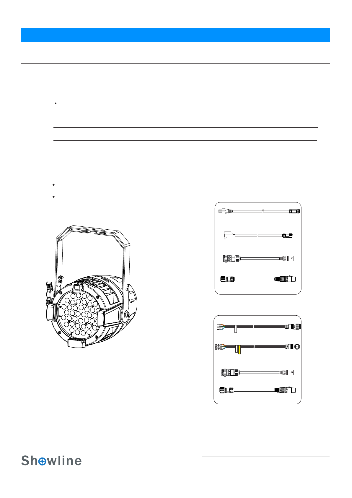
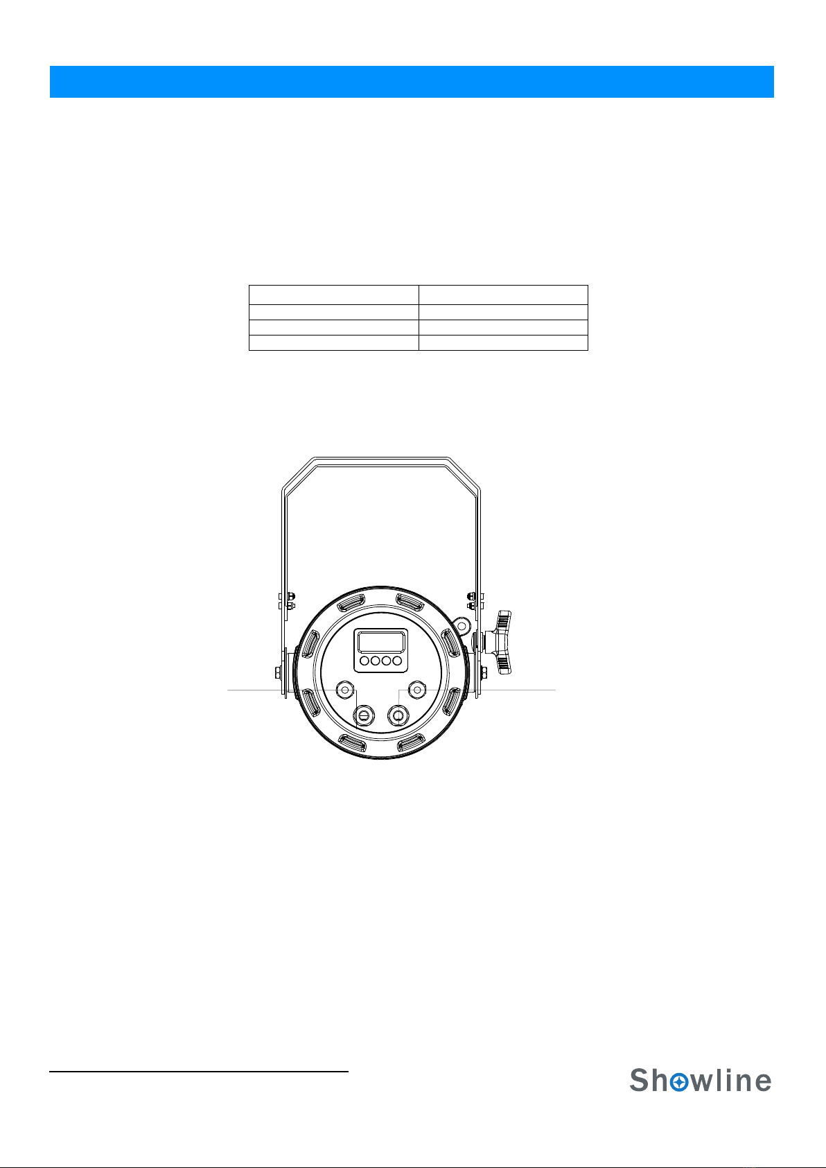
1.SL ParBlazer 100 UV COMPONENTS
Common Luminaire Components
LCD Display / Menu System
Front of luminaire
Rear of luminaire
UV LEDs
Yoke
Tilt Knob
LCD Display / Menu System
SL ParBlazer 100 UV OVERVIEW
Safety Cable
Anchor Point
Figure 1: SL ParBlazer 100 UV Common Components
Installation & User’s Manual
DMX512/
AC Input
RDM Input
DMX512 /
AC Output
RDM Output
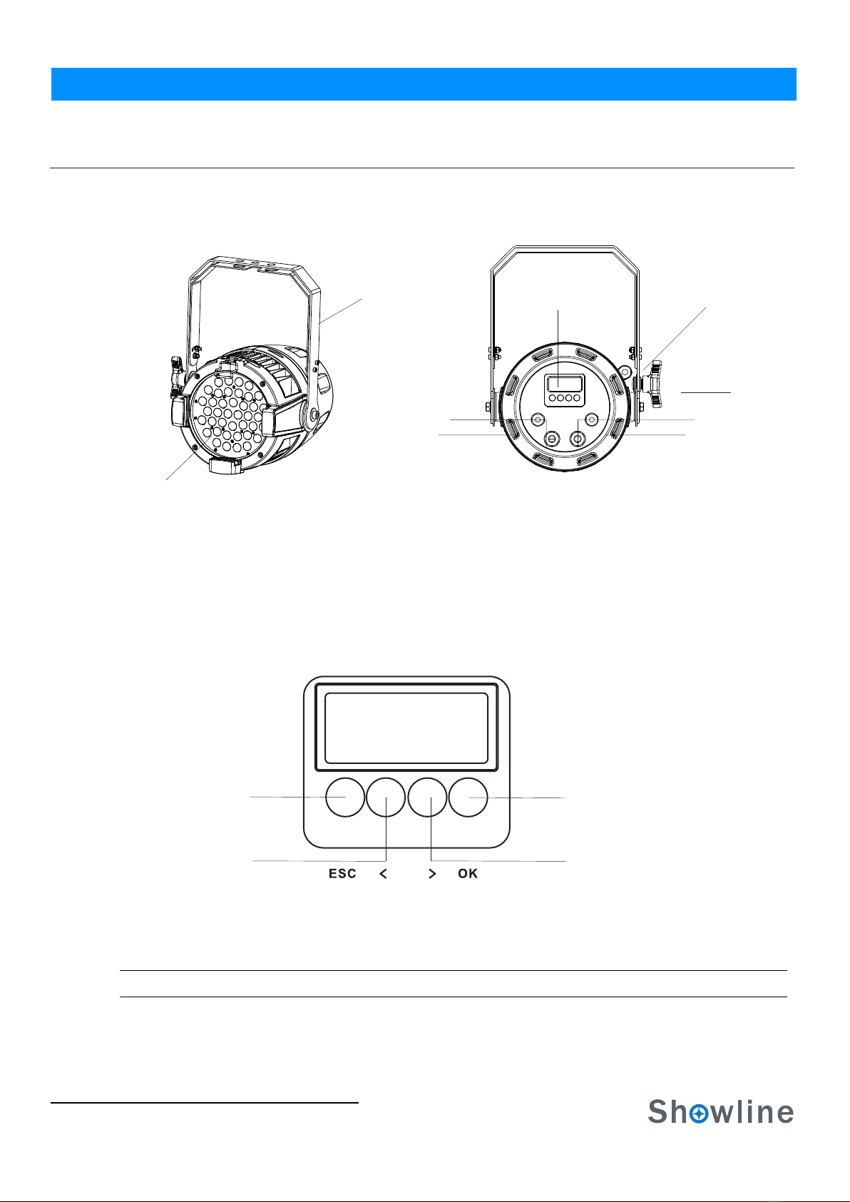
Figure 2: LCD Display & Menu System
Note: For Menu operation and programming details, refer to "LCD Display and Menu System" on page 9.
LEFT Arrow Button RIGHT Arrow Button
CHECK MARK(OK) Button
EXIT Button
SL ParBlazer 100 UV
5
Installation and Set Up
INSTALLATION AND SET UP
1. Power Requirements
The SL Pa rBlazer 100 UV Luminaire operates on AC input voltages from 100 to 240 VAC.
WARN ING! The SL ParBlazer 100 UV luminaire does not have an ON/OFF switch. Always disconnect power input cable
to completely remove power from the luminaire when not in use.
AC Power Operation
When connected to an AC source, the luminaire operates on 100 to 240 volts AC (+/- 10%, auto-ranging). The luminaire
contains an auto-ranging power supply. Each luminaire can draw up to 100 Watts.
WARN ING! The maximum amount of fixtures that may be daisy-chained is (A) 10 luminaires 100 ~ 120VAC or (B) 23
luminaires 230 ~ 240VAC (15 Amps).
Note: For wiring of AC input connector, refer to "Connecting SL ParBlazer 100 UV to AC Power" on page 6.
2. Connecting Power
Luminaires can be powered in one of two ways:
Direct connection to an AC power source using an AC input cable. For wiring of the AC input connector, refer to
Connection from the AC output of another SL ParBlazer 100 UV. When using this method, it is very important not
to connect any other type of equipment.
WARN ING! Only connect other SL ParBlazer 100 UV luminaires to the AC Output (Thru) connector of
Installation & User’s ManualSL ParBlazer 100 UV
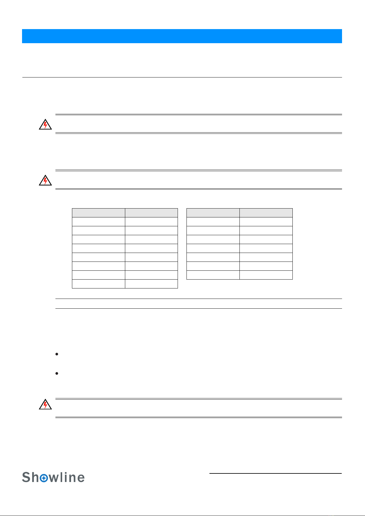
Table 1: SL ParBlazer 100 UVVoltage (VAC) vs. Current*
"Connecting SL ParBlazer 100 UV to AC Power" on page 6.
100 180 0.561.00
110 190 0.53
0.91
160 240 0.420.63
150 230 0.430.67
140 220 0.45
0.71
130 210 0.480.77
120 200 0.50
0.84
170 0.59
Voltage (AC) Voltage (AC)
Total Current (A) Total Current (A)
SL ParBlazer 100 UV luminaire.
Connecting SL ParBlazer 100 UV to AC Power
6
Connecting the SL ParBlazer 100 UV to AC Power
Table 2 describes how to connect power to your SL ParBlazer 100 UV. Field wiring of the SL ParBlazer 100 UV LED
The following wiring scheme is required:
Figure 3: SL ParBlazer 100 UV AC Input & Output Connections
Luminaire
Brown Main/Line(100 to 240VAC)
Blue Neutral
Green/Yellow Ground (Earth)
Table 2: SL ParBlazer 100 UV AC Input/Output Connections
Installation & User’s Manual
Wire Color Purpose
Luminaire is straight-forward. A total of 3 wires/conductors need to be brought to the luminaire.
AC Input AC Output
SL ParBlazer 100 UV

Connecting to the DMX512 Network 7
3. Connecting to the DMX512 Network
Basic DMX512 installation consists of connecting multiple SL ParBlazer 100 UVs together (up to 32 luminaires) in
"daisy-chain" fashion. A cable runs from the control console (or DMX512 control source) to the DMX connector
on the first SL ParBlazer 100 UV. Another cable runs from the other DMX connector on the first luminaire to
a DMX connector on the next SL ParBlazer 100 UV (or DMX512 device to be controlled).
Figure 4: SL ParBlazer 100 UV DMX512 Input / Output Connections
Note: For more information on DMX512 networking and systems, refer to "Additional Resources for DMX512" on
page 1 "DMX CONTROL" on page 14. For SL ParBlazer 100 UV DMX Mapping, refer to .
Figure 5: SL ParBlazer 100 UV- DMX512 Connections
Luminaire
DMX512
DMX512 (out from first
to second luminaire)
DMX512 (out to the next
(from console or
control device)
DMX512 Conections
Note: Remaining pins on each connector are not used.
Installation & User’s ManualSL ParBlazer 100 UV
luminaire or DMX512 controlled
device)
DMX512 Signal
Common (Drain)
DMX512-
DMX512+
XLR Pin Color
1
2
3Red
White
Black
DMX512/
RDM Input
DMX512/
RDM Output
Mounting Luminaire
8
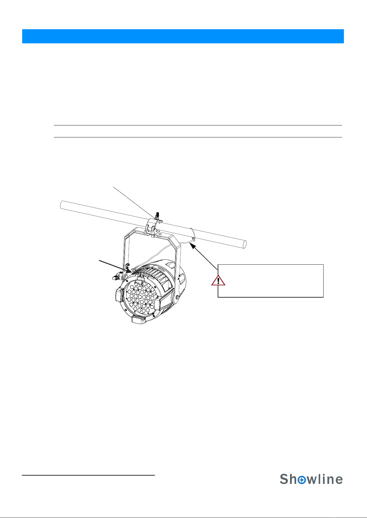
4.Mounting Luminaire
Truss / Hanging Applications
The SL ParBlazer 100 UV is provided with the ability to hang via truss hooks, clamps, etc. (sold separately). Simply
attach hook, clamp, etc. to the SL ParBlazer 100 UV yoke through the provided M12 holes. It is recommended
(and may be required by local and national safety codes) to use and install a safety cable (sold separately) as illustrated in
Figure 6. When hanging the fixture, be sure to leave enough space around the luminaire to allow proper, uninterrupted
airflow for cooling and movement. Refer to for spacing (dimensional) requirements."Luminaire Dimensions" on page 20
Note: Mounting hooks, clamps, safety cables, etc. are sold separately or by others.
.
Figure 6: Mounting the Fixture - Hanging Applications
Floor Mounting
The SL ParBlazer 100 UV are designed to sit directly on its split yoke assembly in a floor installation application.
When used in this type of application, be sure to leave enough space around the luminaire to allow proper, uninterrupted
airflow for cooling and movement.
Installation & User’s Manual
Safety Cable Anchor Point
Truss Hook or Clamp
(sold separately)
SAFETY CABLE: Is sold separately and
recommended for all hanging installation and
may be required by national and local codes.
Use the safety cable anchor point for this fixture.
SL ParBlazer 100 UV
Table des matières
Autres manuels Showline Projecteur

Manuels Projecteur populaires d'autres marques

VIZULO
VIZULO Micro Martin Guide de l'utilisateur

EuroLite
EuroLite LED IP FL-100 SMD Manuel utilisateur

Cooper Wheelock
Cooper Wheelock XB12 Manuel utilisateur

Allen + Roth
Allen + Roth 17624-000 Manuel utilisateur

ADJ
ADJ 4 STAGE PAK Manuel utilisateur

Cooper Lighting
Cooper Lighting EGL91SW233 Manuel utilisateur


