
Shivaki STV-32LED13 Manuel utilisateur

STV-32LED13/STV-32LED13W)
STV-40LED13/ STV-40LED13W)
Service Manual

1
Contents
1. Safety precautions
2. Technical specifications, characteristics and functions
3. LCD structural diagram
4. Description of major components of LCD
5. Failure analysis
6. Simple adjustment
7. List of assemblies
2
I. Safety precautions
▲ It is strictly prohibited to place this unit in open air or damp places in order not to
cause internal short-circuit firing or electroshock risk.
▲ It is strictly prohibited to place this unit on an unstable cart, ramp or table to
prevent this unit from dropping, which may cause injury of human being.
▲ High voltage exists in the unit. Only the professional staff familiar to the service
manual and board conditions of this unit can open the enclosure for repair.
Note: This service manual should be read and used by the professional
staff only. Prior to any repair work, the inspectors must read the safety
precautions in this manual.
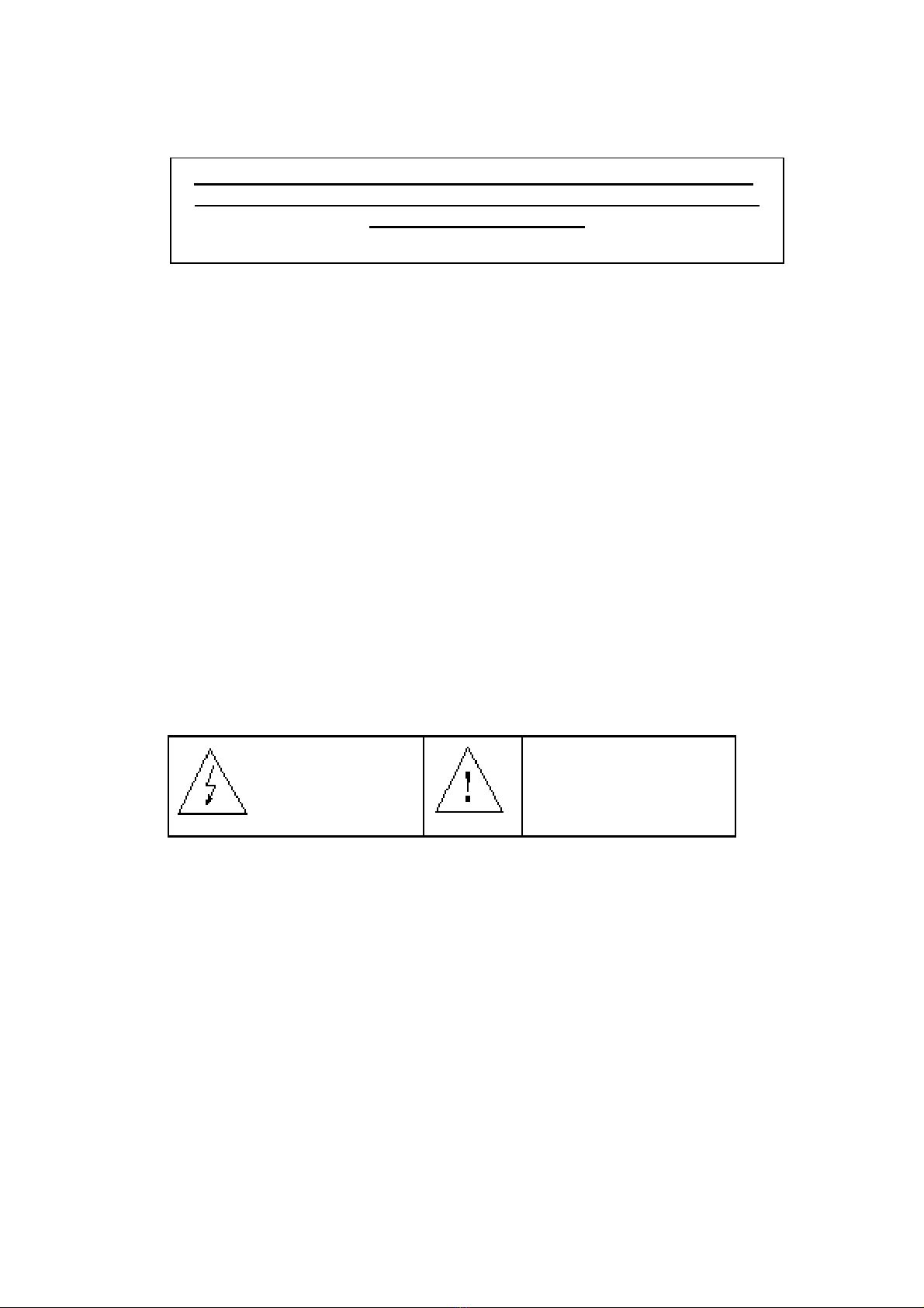
This symbol indicates:
High voltage danger.
Protect against
electroshock.
This symbol indicates: Safety
components in the equipment
cannot be replaced at will
during the service.
3
General rules:
1. Before the rear cover is opened for repair, the unit must be placed horizontally on
a soft surface with no static charges.
2. Before the chassis are repaired (with power on), a 1:1 isolation transformer should
be connected between the AC power supply and this unit.
3. Prior to the repair, inspect the parts in the high-voltage circuits and the initial
connection of the circuits. Any connectors or elements damaged due to the short
circuit should be replaced.
4. Considering the safety of the product, any replacement parts should be within the
scope of the technical specifications indicated in the service manual. Only the
printed circuit board diagram numbers designated in the service manual can be
used as replacement.
5. After the repair, all the protection components should be checked for correct
installation, and the initial connection mode should be confirmed.
6. Before the cover is closed, check that there are no loose parts in the unit.
7. After the repair, perform the following inspections of withstand voltage and
insulance to avoid electroshock.
Method of inspections:
Pull out the AC power cable for connecting the power supply and the
connection receptacle of this unit.
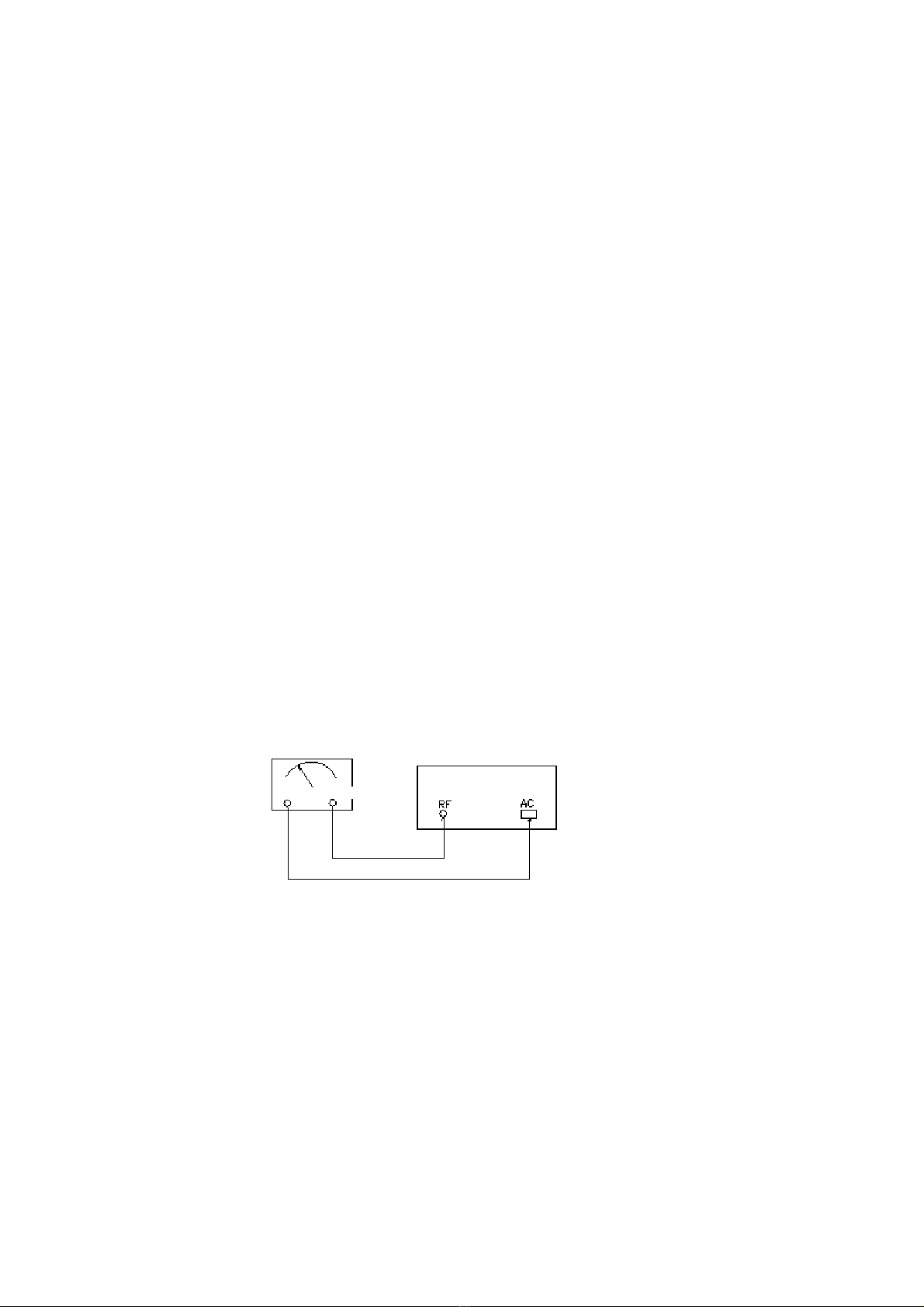
Switch on the power switch of the TV. Connect ZHZ4B withstand voltage and
insulance testing set and the PDP TV as shown in the following diagram:
Set the insulation at 4MΩ/500V. Set the time as 4 seconds. Set the reading of
withstand voltage as 1.5KV. Set the leakage current as 5mA. And set the time
as 1 minute. No alarming signals should appear in the testing set during the
above testings.

4
II. Technical performance
STV-32LED13/STV-40LED13 is a high-definition color TV receiver that
integrates modern electronic technology, communication technology, information
processing technology and high-speed numeric picture processing technology.
(I) technical specifications:
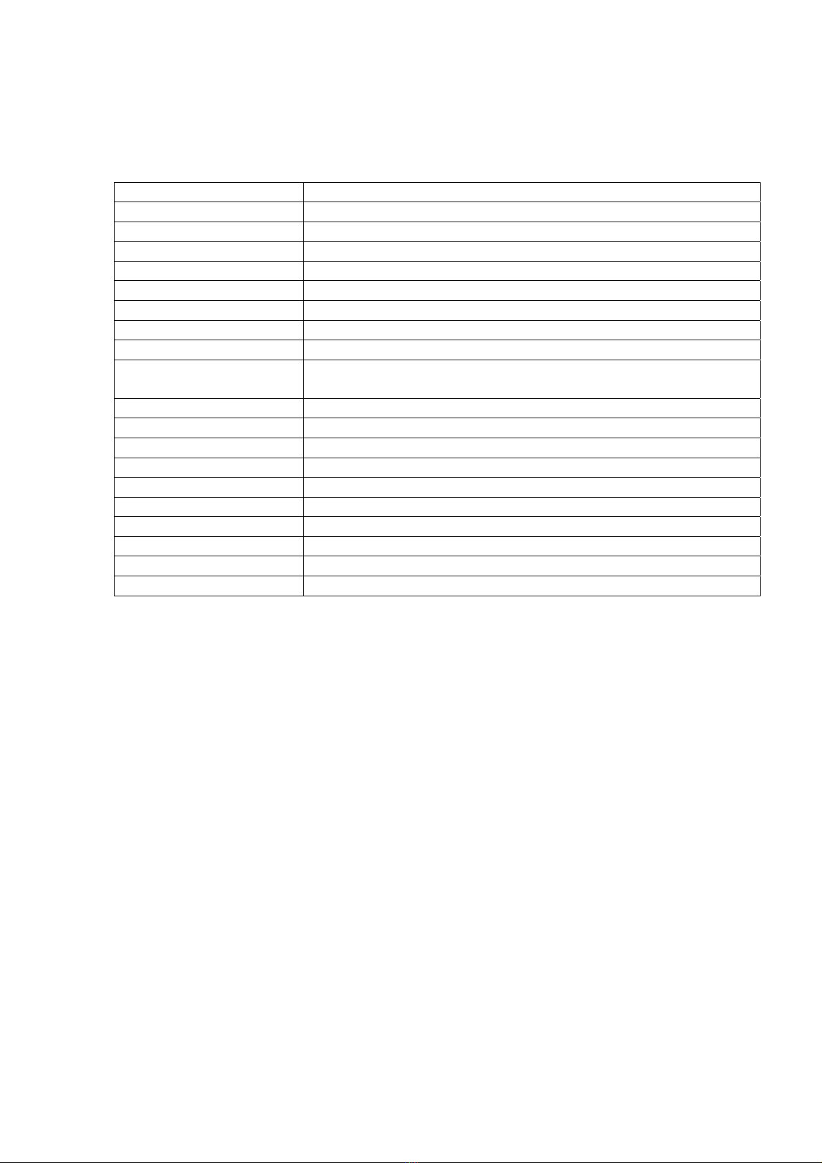
Type STV-32LED13/STV-40LED13
Broadcasting signal
system
PAL /SECAM DVB-T/T2 DVB-S/S2
Video signal system Video PAL/NTSC/SECAM
Stored program ATV 99 ;DTV 1200 (DVB-T+ DVB-C dynamic )
5000 (DVB-S/S2 dynamic )
Radio frequency RF input impedance: 75Ω
Video frequency VIDEO input impedance:75Ωinput voltage:1Vp-p±10%
RGB input impedance:75Ωinput voltage Y:0.7Vp-p±3db
YPrPb input impedance:75Ωinput voltage Y:0.7Vp-p±3db
Audio input voltage:0.2-2Vrms
Audio output
(speaker)
2×8W (impedance 8Ω)
Power supply 100V~240V~ 50/60Hz
Standby power
consumption
0.5W
Aspect ratio 16:9
Operating temperature 0~40℃
Relative humidity ≤80%
(II) Technical characteristics
1. high-definition
2. high contract
3. high brightness
4. Multiple input mode display
5. Point-to-point display with no flickering
6. High-resolution computer interface, the largest support 1366*768
resolution module
7. Super-thin type appearance design
8. Infrared remote control
9. Open-type function menu
5
(III) Major functions of this unit
1. This unit can control the application functions through the various infrared
transmitting commands of the remote control.
Name Function
POWER Standby on/off
SOURCE TV / VIDEO input status selection button
MUTE Mute on/off
DISPLAY The signal information
SLEEP Sleep timing off
MENU Menu selection/exit
CH+ Increase program number/Display the previous menu
CH- Decrease program number/Display the next menu
V+ Increase volume/Increase the item value /Enter the menu
rightward/ confirmation
V- Decrease volume /decrease the item value
1,2,3,4,5,6,7,8,9,0 Number selection
6
III. LCD structural diagram
Structural diagram (see Attached sheet I)
IV.Description of the major components
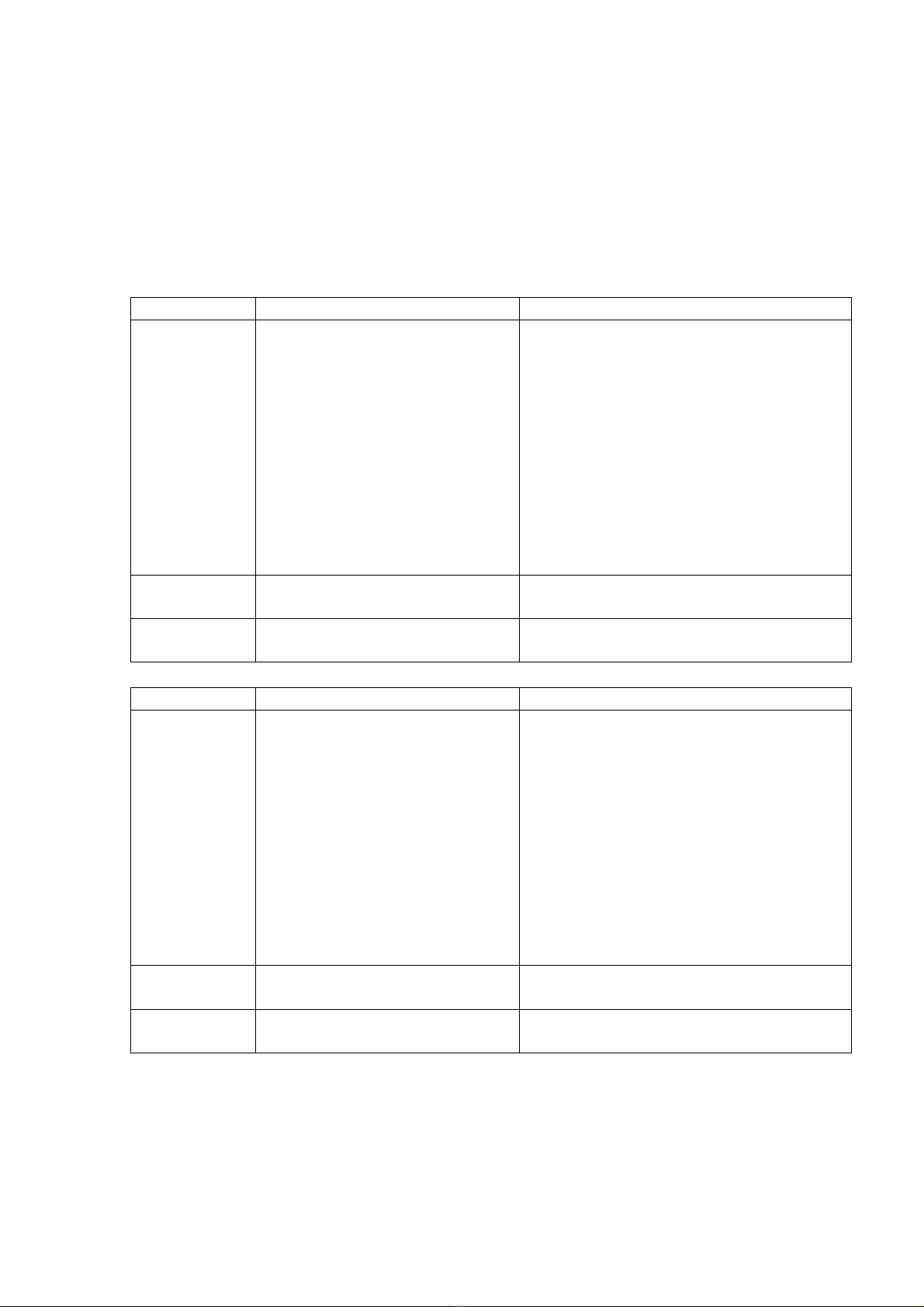
(I) Printed circuit board:
Name Printed circuit board No. Main Functions
Mainboard A920326@
(Printed Board No.
TP.S512.PB83(80V/320mA))
Is a board which is integrated with power
supply,LED driver and TV board.
Is an analog and digital TV control board,
which is suitable for Pan-European
market.
USB slot can be used for software
upgrade, and multimedia play.
HDMI 1.4a compliant , HDCP 1.2
compliat.
Power part is a high efficiency DC-line
switching power supply unit.
Remote
control board
5069782@
IR signal receiving and transmission
Button
control board
5069783@
button receiving and transmission
Name Printed circuit board No. Main Functions
Mainboard A920327@
(Printed Board No.
TP.S512.PB83(80V/480mA))
Is a board which is integrated with power
supply,LED driver and TV board.
Is an analog and digital TV control board,
which is suitable for Pan-European
market.
USB slot can be used for software
upgrade, and multimedia play.
HDMI 1.4a compliant , HDCP 1.2
compliat.
Power part is a high efficiency DC-line
switching power supply unit.
Remote
control board
5069782@
IR signal receiving and transmission
Button
control board
5069783@
button receiving and transmission

7
(II) LCD display screen:
Refer to the LCD specification (see the annex)
(III) Instructions of main components:
I. High-frequency tuner:
1) Radio frequency receiving and demodulation;
2) PAL/SECAM analog television and DVB-T , DVB-S2digital
television
3) FS (Frequency Synthesize);
4) IIC control;
5) Integrated image middle-frequency demodulation, outputting full
TV signal video and audio.
II. Video processing
Video digital decoder TP.S512:
1) 3-D motion adaptive video de-interlaces with edge-oriented adaptive
algorithm for smooth low-angle edges.
2) MStar 3rd Generation Advanced Color Engine (MStarACE-3) automatic
picture enhancement gives: Brilliant and fresh 、Intensified contrast and
details.
3) High-quality analogue to digital conversion circuit ADC, self-adaptation
clamp and automatic gain control AGC.
4) Horizontal linear and non-linear zooming.
5) Supports up to 8/10-bit dual LVDS full-HD(1920*1080) panel interface.
6) Display and scanning control. Contrast, brightness, color saturation, tone
control..
7) Support USB2.0 multimedia play, support audio and video play, support txt
and picture browse.
8
V. Failure analysis:
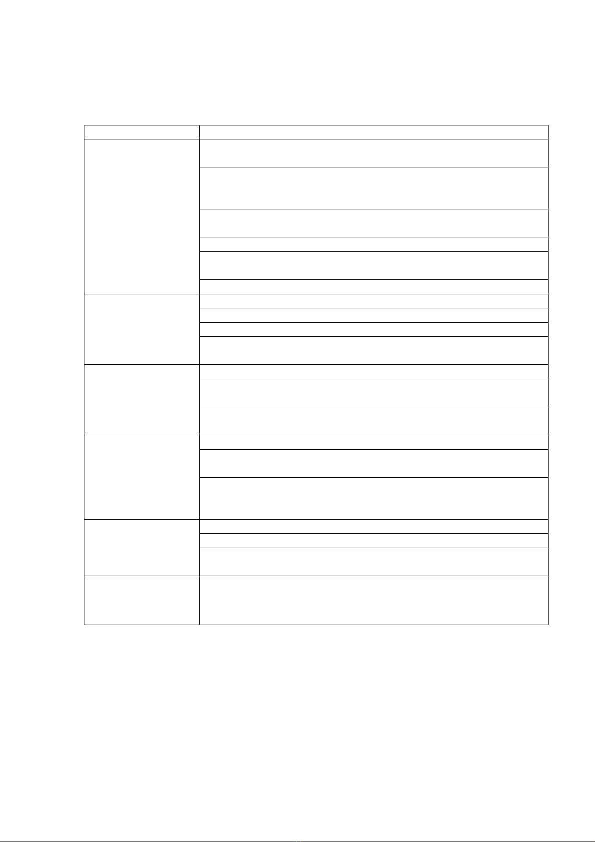
Main failure analysis diagram (see Attached sheet IV)
1. Common failures:
Other failures Analysis procedure
Image and
accompanying sound
are interfered.
Inspect if the direction, position and connection of the antenna is
proper.
Inspect if the signal sources are inputted stably under the current
playing status with no interference.
Check if the signal wires are grounded properly.
Check if there is any interference of electrical equipment near the
unit.
Check if the power voltage inputted is stable.
Check if there are any buildings that reflect the broadcasting
electromagnetic waves in the TV receiving environment.
Start up and check if the various options are all correct.
With static pictures
but no images and
accompanying sound
Check for proper signal insertion.
Check if the remote control functions properly.
Check for correct settings of image and volume.
Switch off and open the cover of the unit to check the signal terminal
board.
After a period of TV
receiving, the unit
will be switched off.
Check if the TV signal is inputted properly under such phenomenon.
Click the “MENU” key of the remote control and check for correct
selection of the timed shutdown item.
Check if it is caused by the computer connected. If a computer is
connected, set the power-saving setting of the computer to “off”.
No color image Check for proper signal source inputted currently.
Open the menu system and click the remote control’s “MENU” key.
Check for correct selection of the items concerning images.
Switch off. Open the cover of the unit and check for proper contact of
the data connection wire between the data conversion board and the
display screen.
Malfunction of
remote control
Check the polarity of the batteries placed in the remote control.
Check if the batteries in the remote control are effective.
Check the transmitting window of the remote control and the remote
sensor window of the unit
Others Even the image and sound of the unit are normal, the enclosure will
expand and sounds will be given once in a while along with the
variation of the ambient temperature. This is normal.
9
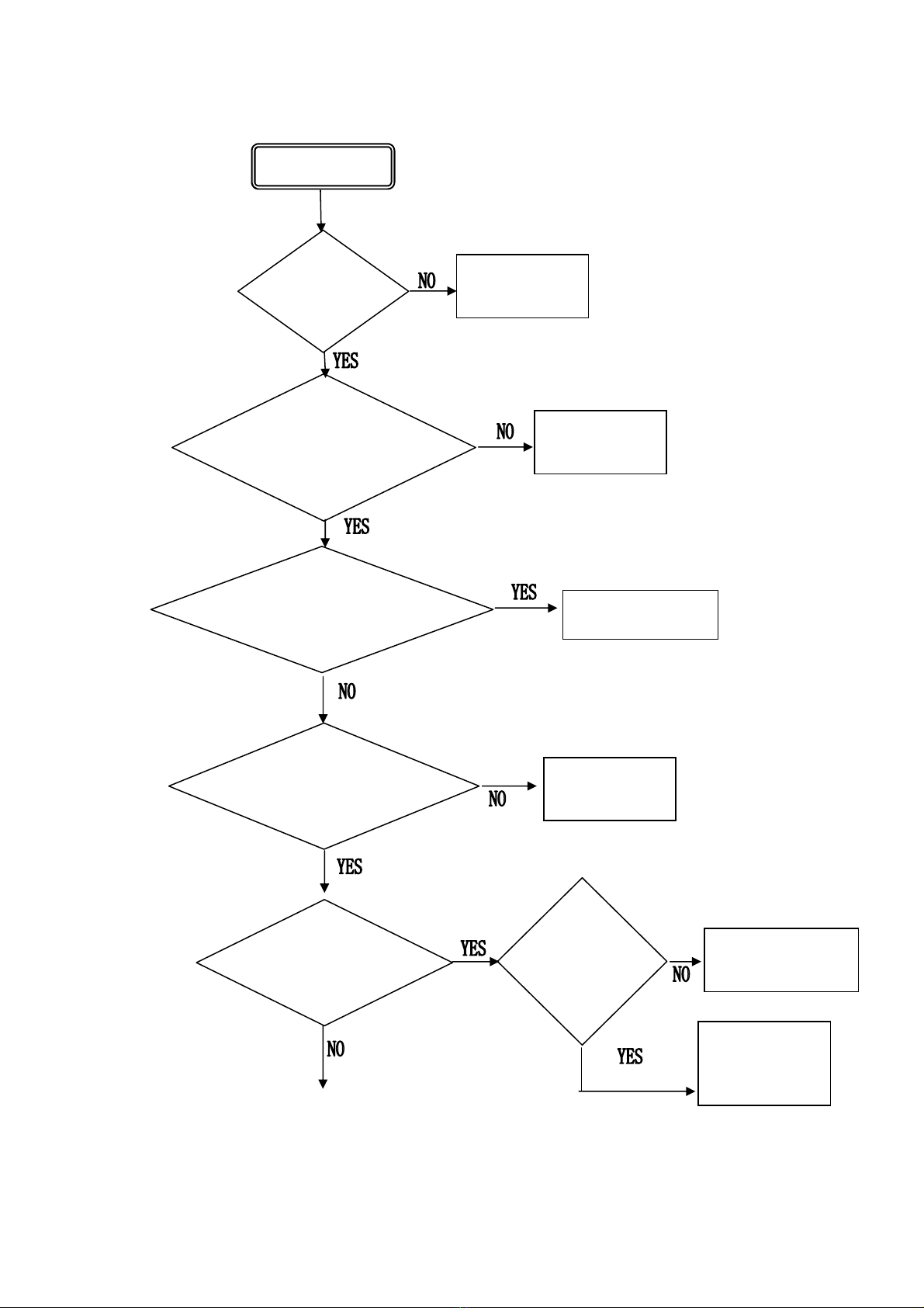
2. Perform failure analysis with the “Operation Instruction” used correctly:
No raster
If the power
supply cable is
connected
properly
Power supply
cable plug and
receptacle
If the input voltage and
frequency is consistent
with those of the unit
Ensure the correct
input of power
supply
If the unit is in standby
status (remote control
judgment)
Check if the currently
received video signals
are inputted correctly
Press POWER button
for startup
Check the
exogenous signal
sources
Judge if the unit is
in blue background
Switch it off
and wait for 2
minutes.
Restart and
see if it can be
restarted.
Remove the cover
and replace the
mainboar
d
Then OK. The
failure may be
poor contact.
Ce manuel convient aux modèles suivants
3


