SD16A Instruction Manual
8
8. Specification
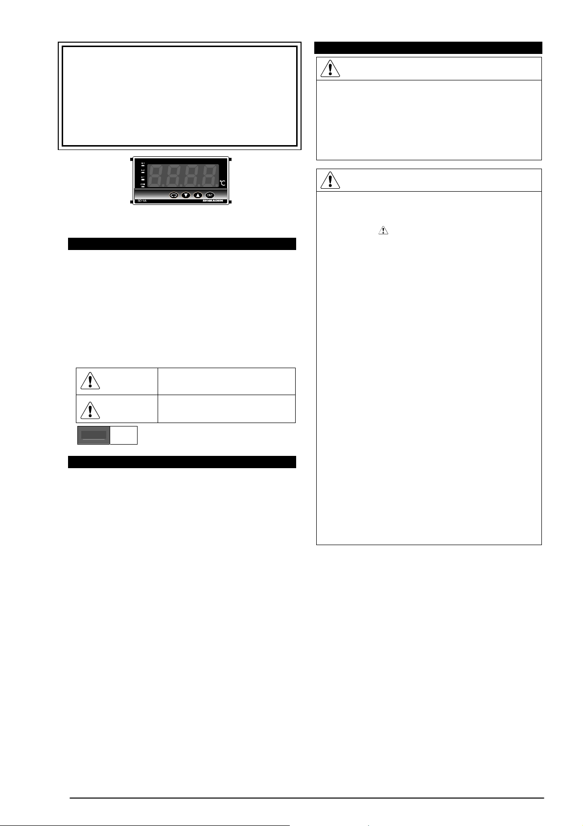
Display
Digital display Measured value (PV), 7-segment, Red 4-digit LED
Action indication SET (green) : lit when parameter value is displayed
COM (green) : lit when communication mode is set
AL1/AL2 (red) : lit when alarm signal is output
Display accuracy ± (0.3%FS + 1 digit) within measuring range
Excluding cold junction temperature compensation accuracy
of thermocouple input.
± 5%FS for temperature below 400°C (752°F) of
thermocouple B.
Accuracy of thermocouple T or U is ±0.5%FS at above -100°C
and 0°C or below, and ±1%FS at -100°C or below.
Display accuracy
maintaining range 23°C±5°C (18 ~ 28°C)
Display resolution Differs depending on the measuring range (
0.001, 0.01, 0.1, 1
)
Measured value
display range
-10 ~ 110% of measuring range (Accuracy is only guaranteed
when the value is within the measuring range).
For R.T.D. input of -199.9 ~ 600.0°C: -240.0 ~ 680.0°C
-199.9 ~ 500.0°C: -240.0 ~ 570.0°C
For thermocouple K of -199.9 ~ 800.0°C: -273.1 ~ 900.0°C
Display update cycle 0.25 ~ 5.00 secs (0.25 secs step)
When 0.50 secs or more is set, a difference may occur among
the displayed value, the analog output, and the
communication data.
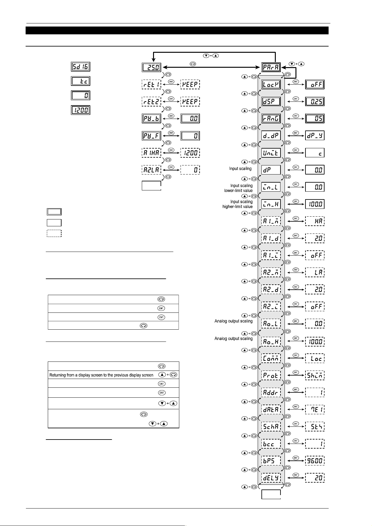
Setting
Setting method Using four key switches on the front panel
Setting protection feature by key lock ON/OFF is provided.
Setting range Same as the measuring range.
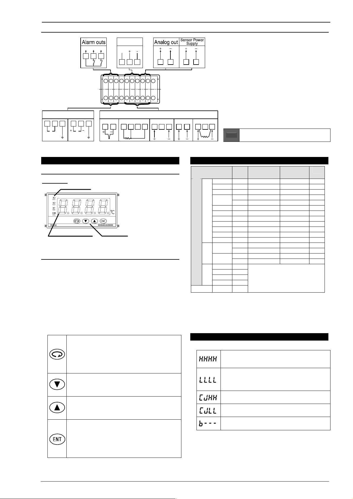
Input
Input type Thermocouple, R.T.D., voltage (mV/V). Universal-input
Thermocouple B, R, S, K, E, J, T, N {U, L (DIN43710)}, WRe5-26
For details, refer to the Measuring range code table.
Lead wire tolerable
resistance 100Ω max.
Input impedance 500kΩ min.
Burnout Standard feature (up-scale)
Cold junction
compensation
accuracy
±1°C (within accuracy maintain range (18 ~ 28°C))
±2°C (ambient temperature 5 ~ 18°C, 28 ~ 45°C)
R.T.D JIS Pt100 3-wire type, JPt100 3-wire type
Amperage Approx. 0.25mA
Lead wire tolerable
resistance 5Ω max./wire (each wire should have the same resistance)
mV 0 ~ 10mV DC
-
l
o
V
e
g
a
t
V0 ~ 5, 1 ~ 5, 0 ~ 10V DC
Input impedance 500kΩ
min.
Current 4 ~ 20mA DC
External receiving
resistor 250Ω (supplied if specified)
Input scaling
function
Available in case of voltage (mV/V) or current (mA) input.
Reverse scaling can be set.
Scaling range -1999 ~ 9999 counts
Span 10 ~ 10000 counts
Decimal places None, 0.0, 0.00, 0.000
Sampling cycle 0.25 secs
PV bias -1999 ~ 2000
PV filter 0 ~ 100 secs (PV filter is set to OFF when 0 sec)
Isolation Isolated between input and analog output (sensor power
supply), or between input and communication.
Not isolated between input and system.
Alarm output (option)
Number of alarm
points
2 points (AL1 and AL2), normally open, COM is commonly
used.
Alarm type One of the following six types can be assigned to each alarm.
None, higher-limit absolute value alarm (with latching),
higher-limit absolute value alarm (without latching), lower-limit
absolute value alarm (with latching), lower-limit absolute value
alarm (without latching), Scale over
Setting range Within measuring range or within scaling range
Alarm action ON-OFF action
Hysteresis 1 ~ 999 Unit
Inhibit action ON/OFF can be selected for each alarm output.
Output type Contact 1a (COM is commonly used)
Rating 240V AC 1.5A (resistive load)
Output update cycle 0.25 secs
Isolation Isolated between alarm output and input, between alarm
output and analog output (sensor power supply), between
alarm output and communication, or between alarm output
and system.
Not isolated between alarm output 1 and alarm output 2.
Analog output (option)
Analog output type 0 ~ 10mV (Output resistance 10Ω)
0 ~ 10V (Load current 1mA max.)
4 ~ 20mA (Load resistance 300Ω max.)
Output resolution Approx. 1/14000
Output accuracy ±0.3%FS of display value
Scaling Within measuring range or within input scaling range (reverse
scaling can be set).
Output update cycle 0.25 secs
Isolation Isolated between analog output and input, between analog
output and alarm output, between analog output and
communication, or between analog output and system.
Sensor power supply (option)
Output rating 24V ± 3V DC 25mA max.
Depending upon instrument’s power ON-OFF status.
Isolation Isolated between sensor power supply and input, between
sensor power supply and alarm output, between sensor power
supply and communication, or between sensor power supply
and system.
Restrictions Sensor power supply can't be selected when the analog
output is selected. Sensor power supply can’t be selected
when the power supply 24V is selected.
Communication (option)
Communication type RS-232C, RS-485
Communication
system Half duplex asynchronous communication method
Communication
speed 1200, 2400, 4800, 9600, 19200 bps
Data format 7E1, 7E2, 7N1, 7N2, 8E1, 8E2, 8N1, 8N2
Communication
address 1 ~ 100
Number of
connectable devices 31 devices max. (for RS-485)
Delay 1 ~ 100 msec
Communication
protocol
Shimaden standard protocol, MODBUS ASCII, MODBUS
RTU (start character and BCC operation method can be
selected for Shimaden standard protocol).
Isolation Isolated between communication and input, between
communication and alarm output, between communication
and analog output (sensor power supply), or between
communication and system.
Miscellaneous
Data storage By nonvolatile memory (EEPROM).
Temperature -10 ~ 50°C
Humidity 90%RH max. (no dew condensation)
Height 2000m above sea level or lower
Installation
category II
s
n
o
i
t
idn
o
c
tn
e
ibm
A
e
s
u
r
o
f
Degree of
pollution 2
Power supply voltage
(frequency)
100 ~ 240V AC ± 10% (50/60Hz)
24V AC (50/60Hz) /DC ±10% (option)
Power consumption 11VA (100 ~ 240V AC)
8VA (24V AC)
5W (24V DC)
Safety IEC61010-1, EN61010-1
-i
l
p
pA
elb
ac
dr
a
dn
a
t
s
EMC EN61326:1997+A1:1998, A2:2001, A3:2003
EMC testing display accuracy ±3%FS
Dust proof /drip proof IP66 equivalent
Isolation resistance Between all input/output terminals and power terminal:
500V DC 20MΩ min.
Between all input/output terminals and ground terminal:
500V DC 20MΩ min.
Dielectric strength Between all input/output terminals and power terminal:
2300V AC for one minute.
Between power terminal and ground terminal:
1500V AC for one minute.
Case material Black PPO resin molding (equivalent to UL94V-1)
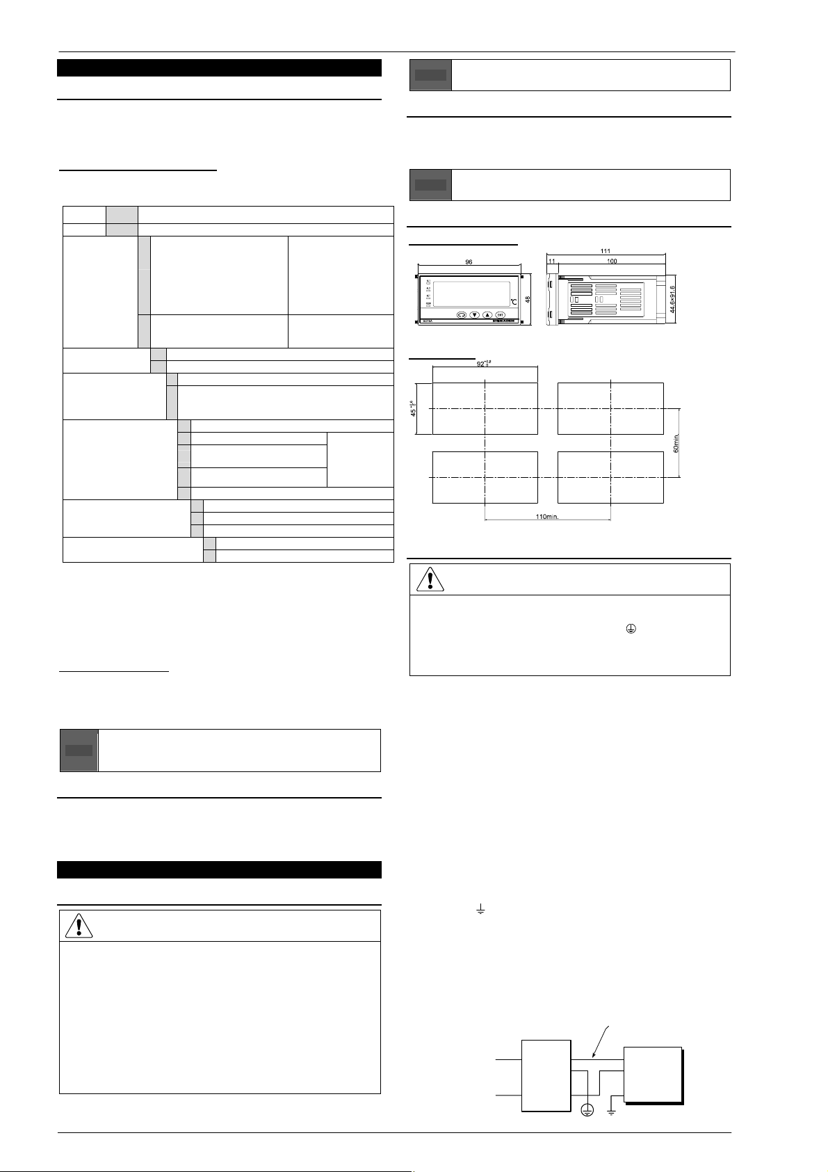
External dimensions H48 x W96 x D111 mm (inside of panel: 100mm)
Mounting Push-in panel (one-touch mount)
Panel thickness 1.0 ~ 4.0 mm
Panel cutout H45 x W92 mm
Weight Approx. 250g
The contents of this manual are subject to change without notice.
Any questions should be directed to your local agent, or send an e-mail to exp-dept@shimaden.co.jp.
Printed in Japan