
Sharp WH-236E Manuel utilisateur

SHARP SERVICE MANUAL
ELECTRIC WATER HEATER
MODELS WH-236E
WH-239EP
WH-246E
SHARP CORPORATION
TABLE OF CONTENTS
PARTS IDENTIFICATION AND SPECIFIC INFORMATION ..............................................
EXTERNAL DIMENSION ...................................................................................................
CAUTION FOR USE ..........................................................................................................
HOW TO USE ....................................................................................................................
WIRING DIAGRAM ............................................................................................................
INSTALLATION ADVICE ....................................................................................................
POWER SUPPLY INSTALLATION .....................................................................................
SHOWER SET ...................................................................................................................
REPLACING METHOD FOR MAIN PARTS ......................................................................
TROUBLESHOOTING .......................................................................................................
CIRCUIT DIAGRAM (PCB-1) .............................................................................................
SERVICE PARTS LIST ......................................................................................................
Page
2
3
3
4
5
5-8
8-10
10
11-15
16
17
18-24
In the interests of user-safety (Required by safety
regulations in some countries) the set should be restore
to its original condition and only parts identical to those
specified should be used.

2
PARTS IDENTIFICATION
SPECIFIC INFORMATION
Model
Rated voltage
Rated frequency
Power consumptions
Water supply system
Water temperature control
Minimum pressure
Maximum pressure
Product dimension (W x H x D)
Weight (kg)
IP number
WH-236E WH-239EP WH-246E
Note : Temperature of inlet water is approximately 25oC and flow rate is 2.3 liters/min.
220
50
2.4
3,500 Single point
Electronic control automatic constant
temperature - approximately 50oC (Maximum).
0.02 MPa (0.21 Bar)
0.34 MPa (3.39 Bar)
236 x 378 x 86
IP25
4,500
Main breaker
ELB lamp
Power lamp
Heater lamp
: 1 MPa (Megapascal) = 10.2 Kilograms/Square centimeter.
Power cord and ground wire
Temperature control knob
Shower head
Shower stand
Shower hose
Power SW. button
Main water valve
Water volume knob
ELB button
Body
Breaker angle support
3
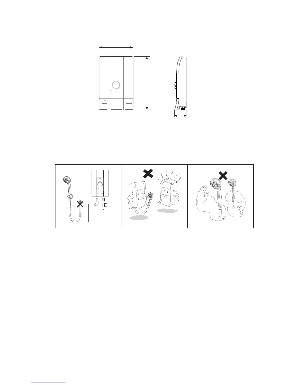
EXTERNAL DIMENSION
Front Side
(Unit in mm.) Fig. 1
236
378
84
1. Always turn off the main breaker before making any repairs to your electric water heater.
2. Do not install water valve or faucet at hot water outlet. (Fig. 2)
3. Do not spray water on this electric water heater or put water towels on it. (Fig. 3)
4. Do not cover the shower head with hands or towels or fold the shower hose. (Fig. 4)
CAUTION FOR USE
Water valve
Water outlet
Water inlet
Fig. 2 Fig. 3 Fig. 4
5. If you see the light within your house is flashing from time to time while showering due to irregularity of
electricity, the water temperature may change and this is not unusual.
6. In case that using other faucet at the same as using electric water heater (common main water pipe),
the water pressure and flow may be reduced and it may cause higher water temperature. This is not
unusual. You should adjust water volume knob or reset temp. control knob in appropriate way.
7. In the event of thunder and lightning storm, turn off the main breaker to prevent the damage that may
occur on this appliance.
8. In the event that ELB light (green) is shut off while electric water heater is operating, lift ELB switch up
completely. However, if ELB light (green) still off, turn off this appliance by press the Power SW. button
then contact your SHARP service facility or SHARP dealer.
9. Close supervision is necessary in order to check on the water temperature when used by children,
elderly, patients and disabled person.
10. In case of tap water outage while using, turn the temperature knob to “OFF” and the water volume
knob to turn off the water (to avoid water automatically flowing when your are not in the bathroom
after tap water flow resumes).
11. If water has stopped flowing, turn off the Power SW. button and ensure that there is no light on the
power lamp (red) and ELB lamp indicator, (To prevent water flow when the unit is unattended after
normal operation of water supply).
12. While we using a product if that is stop working immediately as we do not know the cause, please
inform the SHARP service center for proceed to repair.

ADJUSTMENT WATER TEMPERATURE
1. To use the temp. control knob, turn the knob clockwise and observe the temperature level lamp.
2. Using the water volume knob.
3. Using the Power SW. button.
1.1 If the temperature level lamp does not show, the water will flow at the normal temperature.
1.2 The warm water temperature starts from LOW (the temperature level lamp is yellow) to HIGH
(the temperature level lamp is red). The water temperature is approximately 50oC.
1.3 The control lamp flashing when the power lamp is on means the preset temperature is higher
than water temperature from the main water valve. Gradually reduce the temperature until the
control lamp is on.
1.4 The control lamp and the power lamp are on means the flowing water reaches the preset
temperature.
1.5 The control lamp flashing when the power lamp is off means the flowing water is hotter than the
preset temperature.
Turn the knob clockwise to increase water volume.
Turn the knob counterclockwise to decrease volume.
Press the Power SW. button and the ELB lamp indicator will illuminate and water will flow from
the shower head, press the button again to turn off the heater.
4
HOW TO USE
Temp. control knob
Temp. level lamp
ELB checker button
Heater lamp
Power lamp
ELB lamp
BEFORE USE
The installation work is to be done by the Authorized “SHARP” Dealer.
The electric home shower unit must earthed.
Special skill is required. Never try to repair the unit by yourself.
1. Open the main water valve from the home main water pipe.
2. Open the main breaker switch.
3. Pull the ELB breaker to activate the heater electrical system.
4. Press the Power SW. button on the heater. Normal temperature water will flow and the ELB lamp
indicator (green) will illuminate.
5. Turn the water volume knob clockwise or counterclockwise to increase or decrease water from the
shower head (see the water volume knob detail in water temperature adjustment).
6. Press the temp. control knob and turn button to adjust the desired temperature. The temperature level
lamp will illuminated following the turning. The power lamp (red) will be illuminated and the warm water
will flow from the shower head (see the detail in water temperature adjustment).
7. After use, press the Power SW. button to shut the heater off and water will stop flowing and the
electricity will be cut. For the next use, just simply press the Power SW. button and the water will
flow at the prevailing volume and temperature.
Note : In case of electricity or tap water outage while using, always press the Power SW. button
to stop operation before leaving the bathroom.

WIRING DIAGRAM
5
INSTALLATION ADVICE
1. BEFORE INSTALLATION
Please check water pressure before operating this unit.
Minimum water pressure : 0.02 MPa (0.21 Bar).
Maximum water pressure : 0.34 MPa (3.39 Bar).
Please follow the picture below to check water pressure. Water shall overflow at the end of the
tube within 2.3 meters above the faucet.
2. INSTALLATION THE UNIT
2.1. Preparing installation area.
The unit must be mounted to the wall in a vertical position only. (See in the picture)
Leave this unit away from the wall for both sides more than 200 millimeters.
About 2.3 meters
Fig. 5
Fig. 6
The minimum height of 1.50 meters to the lower edge of the unit must be observed.
Fig. 7
Over 1.50 meters

6
Fig. 10
Screw
Fig. 8
Fig. 9
25 mm.
6 mm.
2.2. Removing the unit cover.
Remove the screw underneath the unit.
Open the cover by lifting from the bottom.
2.3. Mounting the unit to the wall.
Drill two 6 millimeters holes in the wall with approximately 25 millimeters in depth.
Install wall anchors into the holes.
Screw the top wall anchors, leave screw length around 8-10 millimeters and hang the unit on the
screw then marked the position in order to drill another 2 holes at the bottom, drill the holes and
install the rest of wall anchors then fasten all of 4 screws.
2.4. Assemble the cover with the heater.
Assemble the cover from the bottom of the heater and push tight on the top of cover.
Tighten screws to attach the cover with the heater to the same position.
Fig. 11

7
Fig. 12
Notification in connecting the shower hose.
Shower head
Joint
Shower hose
2.5. The shower assembly.
The joint the shower hose counterclockwise with the shower.
2.6. Installation the shower stand.
Ensure that the shower stand located in the level that the top part of the shower head is not
higher than the top part of the unit when hanging the shower head. (See in the picture)
The angle of shower head holder can adjust into 2 levels.
Connect to the unit.
Connect to the shower head.
Fig. 13
3. PIPING INSTALLATION
1. Connection point between the unit and the water volume knob and twist the shower hose by
hands until it tight. Do not use any tools during assembly because it may cause the damage to
plastic components.
2. Tighten the connection into the thread located at the bottom of the water volume knob.
Force gauge do not exceed 40 kgf.cm.
3. Connect water inlet pipe and water outlet pipe as shown in the picture.
Fig. 14
Water inlet
Filter
O-ring
Main water valve
Use pipe at least 15 cm. in length
Shower head
O-ring fixer
Shower hose
Water volume knob

ELECTRIC WIRE CONNECTIONS
1. Be sure to cut off the main power supply switch every time before starting any electrical work
Use dual insulated wire with at least 4 square meters cross-section (WH-236E, WH-239EP).
Use dual insulated wire with at least 6 square meters cross-section (WH-246E).
Connect electric wire to the unit from the main switch board through the main breaker which is
located outside the bathroom. Wire connection must be permanent.
Fig. 15
Earth ground
Main breaker
Bathroom
8
2. Electric wire connection to the unit can be done by 2 methods. (as illustrated) Drill a small hole at the
rubber to insert the wire on side or at the rear of the unit.
Peel the wire and connect to the ELB checker by connecting the high voltage cable to the terminal “L”
and connect neutrons wire into the terminal “N”. Use screwdriver to tighten the wires. (Force gauge
approximately 12 kgf.cm). If the wires are connected into the wrong terminal, the unit will not work
properly. It may result in damage to the circuit or may cause danger to the user.
Connect the wire at rear of the unit.
Fig. 16
Connect the wire on side of the unit.
Fig. 17
(Force gauge 12 kgf.cm)
Ground wire
50 mm.
20 mm.
12 mm. 30 mm.
Ground wire Ground wire

9
3. The ground wire must be connected to grounding point on the unit.
Ground rod installation, select the area where moisture stored in the soil and away from flood area
with no sand or limestone.
The diameter of ground rod is not less than 16 millimeters and the length is not less than
240 centimeters.
Embed the ground rod at least 30 centimeters in depth from ground surface.
Grounding process.
4. Ground resistance must be less than 5 ohm.
5. After grounding process is completed, if ground resistance is higher than 5 ohm, additional ground
rod must be embedded. Leave the additional one away from the previous ground rod at least equal to
the length of ground rod. Connect them together in parallel.
SHOWER SET
Shower heads allow users to adjust into 3 types by simply twisting the shower head cover as show the
picture.
Tools for embedded
At least 30 cm.
Ground surface
Ground rod Fig. 18
Fig. 19
JET TYPE
SPRAY TYPE
COMFORT TYPE
Match the sign with
you designed type.
LEFT RIGHT

10
1. Remove the screw underneath the unit.
2. Open the cover by lifting from the bottom.
3. Now the body is free.
REMOVE OF BODY
Fig. 21
Body
Screw
Back cover
REPLACING METHOD FOR MAIN PARTS
1. Turn out the joint body between the body with the shower hose manually. Never use other tools to
avoid breaking plastic parts.
REMOVE OF SHOWER HOSE
Fig. 20
Body
Shower hose
Ce manuel convient aux modèles suivants
2
Table des matières
Autres manuels Sharp Chauffe-eau


Manuels Chauffe-eau populaires d'autres marques

Kenmore
Kenmore 153.582400 Manuel utilisateur

Applimo
Applimo Edel AIR Manuel utilisateur

STIEBEL ELTRON
STIEBEL ELTRON Eltronom SHU 5 S Manuel utilisateur

clage
clage E-Mini Series Manuel utilisateur

Toyotomi
Toyotomi Oil Miser OM-180 Manuel utilisateur

Bradford White
Bradford White EF Series Manuel utilisateur


