Sharp PJ-ST161 Manuel utilisateur
SHARP SERVICE MANUAL
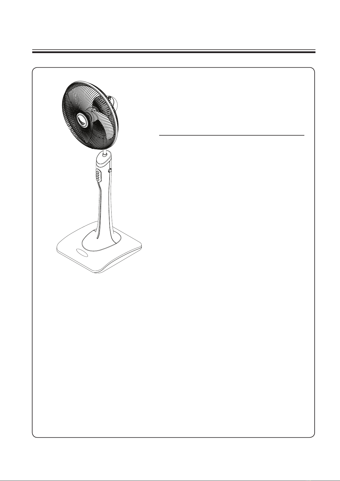
ELECTRIC FAN
MODEL PJ-ST161
In the interests of user-safety (Required by safety
regulations in some countries) the set should be restore
to its original condition and only parts identical to those
specied should be used.
SHARP CORPORATION
TABLE OF CONTENTS
PARTS IDENTIFICATIONS AND SPECIFIC INFORMATION ................................................
CAUTIONS FOR USE ............................................................................................................
CLEANING AND MAINTENANCE ..........................................................................................
WIRING DIAGRAM AND CIRCUIT DIAGRAM .......................................................................
COMPONENT REPLACEMENT PROCEDURE .....................................................................
TROUBLESHOOTING ............................................................................................................
SERVICE PARTS LIST ...........................................................................................................
Page
2
3
3
4
5 - 10
11
12 - 16

2
Model
Rated voltage (V)
Rated frequency (Hz)
Power consumption (W)
Blade (mm)
Rated current (A)
Insulation class
Temperature control
Product dimensions (W x H x D) (mm)
Weight (kg)
PJ-ST161
220
400
0.21
50
46
B
0.70
464 x 1,443 x 421
6.5
Spinner fan
Blade
Base
Wheel
Grille lock nut
Rear grille
Motor bracket
Adjustable tube
Body cover
Adjustable knob
Body
Knob switch
Motor cover
Motor ass’y
Clutch knob
PARTS IDENTIFICATIONS
SPECIFIC INFORMATION
Front grille
Fixing lock

3
CAUTIONS FOR USE
1. Do not disassemble or repair the electric fan by yourself, it may cause troubles such as a re of electric shock.
Consult your nearest dealer.
2. Incase the power cord is broken, it must be replaced by manufacturer or appointed service providers or
equivalent professionals to avoid any damages.
3. Unplug every time before start to clean the parts or when you do not use the electric fan anymore.
4. Do not immerse the electric fan in water or sprinkling water because this could lead or a short circuit or
equipment broken.
5. Do not insert the nger or any objects through the grille while the blade is rotating.
6. Do not spray any vapor or chemicals to the electric fan while the blade is rotating.
7. Plug in tightly in order to avoid the plug to be overheated. This can cause the plastic to be melted, and
conagrated. When unplugging, hold only the plug part; do not pull the cable as this may cause the cable as
this may cause the cable broken.
8. Do not plug in with the wet hand to prevent any injury from the leaking current.
9. While the electric fan is being used, do not plug in the other electric appliances in the same receptacle as
this might cause heat and conagration respectively.
10. Should not use the electric fan close to curtain, mosquito net or any objects which could be pulled to the
motor, otherwise this may cause accident and damage.
11. Should not use the electric fan at the high temperature place such as placing it close to the stove or the high
humidity place, as the unit might be damaged.
12. Should not place the electric fan on the hot or sloped oor, as the unit might be damaged.
CLEANING AND MAINTENANCE
Blade, Front grille and Rear grille
Disassemble, and wipe with damp cloth use cleaning agent mixed with water then dried up with the cloth.
Body
Wipe with damp cloth using water or mild soapy liquid.
Remark
Do not wet electric parts or motor.
Do not clean with chemical substance, thinner and kerosene etc, as this might damage the surface and/or shape
of unit.

4
WIRING DIAGRAM
CIRCUIT DIAGRAM
GEAR BOX
MOTOR ASS’Y

5
REMOVE OF GRILLE ASS’Y
COMPONENT REPLACEMENT PROCEDURE
1. Unlock the xing lock and pull the front grille.
2. Turn the spinner fan clockwise and remove the blade.
3. Turn the grille lock nut counterclockwise and remove the rear grille.
Fig. 1
Fig. 2
Detach the xing lock
to unlock.
Front grille
Spinner fan
Blade
Grille lock nut
Fixing lock
Screw
Base ass’y
Body
Rear grille
Motor ass’y
REMOVE OF BASE ASS’Y
1. Remove the grille ass’y in accordance with “REMOVE OF GRILLE ASS’Y”.
2. Remove 2 screws holding base ass’y and detach the unit from the base ass’y.
3. Now the base ass’y is free.

6
REMOVE OF POWER CORD
1. Remove the base ass’y in accordance with “REMOVE OF BASE ASS’Y”.
2. Remove 2 screws and remove the body cover.
3. Remove 6 screws and separate the front body from back body. (Should be place on jig)
4. Remove 3 screws and cut cord band holding the power cord.
5. Remove the closed terminal and cut the power cord lead wire
from the piano switch ass’y.
6. Now the power cord is free.
REMOVE OF BOTTOM PLATE
1. Remove 2 screws holding base ass’y and detach the unit from the
base ass’y.
2. Remove 6 screws holding the bottom plate.
3. Now the bottom plate is free.
Unit
Jig
Base
Bottom plate
Screw
Fig. 3
Fig. 4
Screw
Screw
Back body
Back body
Front body
Front body
Power cord
Screw
Closed terminal
Cord band
Piano switch ass’y
Lead wire of power cord
Body cover
Unit
Lead wire of motor

7
REMOVE OF PIANO SWITCH ASS’Y
1. Remove the power cord in accordance with “REMOVE OF POWER CORD”.
2. Cut 3 lead wires from the piano switch ass’y.
3. Remove 2 screws holding to the piano switch ass’y.
4. Remove the piano switch ass’y from the body, detach the knob switch and remove the insulation sheet
from piano switch ass’y.
5. Now the piano switch ass’y is free.
Front body
Front body
Knob switch
Insulation sheet
Piano switch ass’y
Piano switch ass’y
Lead wire of piano SW.
Screw
Fig. 5

Adjustable tube
Adjustable housing ass’y
REMOVE OF LOCK SPRING COVER
REMOVE OF ADJUSTABLE HOUSING ASS’Y
1. Remove the base ass’y in accordance with “REMOVE OF BASE ASS’Y”.
2. Remove 2 screws and remove the body cover.
3. Remove 6 screws and separate the front body from back body. (Should be place on jig)
4. Remove 2 screws holding the lead wire motor and cut cord band.
5. Remove the closed terminal and cut the power cord motor from the piano SW. ass’y.
6. Remove 4 screws holding the adjustable housing ass’y and remove from the back body.
7. Remove 2 screws holding the lock spring cover.
8. Now the lock spring cover is free.
1. Remove the lock spring cover in accordance withe “REMOVE OF LOCK SPRING COVER”.
2. Remove the adjustable housing ass’y from the adjustable tube.
3. Now the adjustable housing ass’y is free.
Screw
Screw
Screw
Back body
Adjustable housing ass’y
Lead wire of motor
Power cord motor
Screw
Adjustable tube
Adjustable tube
Lock spring cover
Back body
Front body
Front body
Power cord
Screw
Closed terminal
Cord band
Piano switch ass’y
Body cover
Unit
Fig. 6
Fig. 7
8

REMOVE OF MOTOR ASS’Y
1. Remove the grille ass’y in accordance with “REMOVE OF LOCK SPRING COVER”.
2. Remove 3 screws holding the motor bracket.
3. Remove screw holding to the motor cover.
4. Pull the clutch knob from the motor ass’y and remove the motor cover.
5. Remove the screws holding the link rod to the motor ass’y.
6. Remove the screw holding the motor ass’y to the hinge ass’y and remove it.
7. Now the motor ass’y is free.
Fig. 9
Screw
Screw Screw
Back body
Back body
Reel spring
Adjustable housing ass’y
Motor cover
Motor ass’y
Motor bracket
Screw
Turning axle
Link rod
Knuckle shaft
Screw Hinge
Clutch knob
Screw
9
REMOVE OF REEL SPRING
1. Remove the lock spring cover in accordance with “REMOVE OF LOCK SPRING COVER”.
2. Remove the screw holding the reel spring.
3. Now the reel spring is free.
Fig. 8

REMOVE OF HINGE ASS’Y
1. Remove the motor ass’y in accordance with “REMOVE OF MOTOR ASS’Y”.
2. Remove 2 screws holding the hinge ass’y to the neck.
3. Remove screw holding the link rod to the turning axle.
4. Now the hinge ass’y is free.
Screw
Link rod
Turning axle
Hinge ass’y
Screw
Neck
Fig. 10
10
Table des matières
Autres manuels Sharp Ventilateur


