SGM LEKTRA TC22 Mode d’emploi

TC22/23/24/25
Capacitance level transmitter - electronic preampli•er
technical documentation EN Rev. S

Pag. 2 di 16 www.sgm-lektra.com
TC22÷25 - contents
CONTENTS
1-WARRANTY
2-PRODUCT
3-TECHNICAL FEATURES
4-DIMENSIONS
5-MECHANICAL INSTALLATION
6-ELECTRICAL CONNECTIONS
7-CALIBRATIONS
8-REMOTE VERSION
9-FACTORY TEST AND QUALITY CERTIFICATE
page 3
page 4
page 5
page 6
page 7
page 8
page 10
page 15
page 16

Pag. 3 di 16
www.sgm-lektra.eu
TC22÷25 - warranty
Products supplied by SGM LEKTRA are guaranteed for a period of 12 (twelve) months from delivery date accor-
ding to the conditions specifi ed in our sale conditions document. SGM LEKTRA can choose to repair or replace
the Product. If the Product is repaired it will maintain the original term of guarantee, whereas if the Product is
replaced it will have 12 (twelve) months of guarantee.
The warranty will be null if the Client modifi es, repair or uses the Products for other purposes than the normal
conditions foreseen by instructions or Contract. In no circumstances shall SGM LEKTRA be liable for direct, in-
direct or consequential or other loss or damage whether caused by negligence on the part of the company or its
employees or otherwise howsoever arising out of defective goods.
1-WARRANTY

Pag. 4 di 16 www.sgm-lektra.com
TC22÷25 - product
2-PRODUCT
1. Led indicators
2. Terminals for electrical connections
1.2 IDENTIFICATION
Each instrument has an adhesive identi! cation plate on which are the meter main data. The following picture describes the
information and data on the identi! cation plate.
1. Product code 3. Serial number2. Power supply
1
2
3
4
3. Programming buttons
2. Fixing system to the probe
400A072B - TC22
24Vdc
CCE091501066
2
3
1Mod.
P.S.
S.N.
2

Pag. 5 di 16
www.sgm-lektra.eu
3-TECHNICAL FEATURES
TC22÷25 - technical features
Housing material
Nylon; metallized Nylon
Mechanical fitting
Bajonet (to be insert into IP66/67 enclosure)
IP rating
IP50
Electrical connection
1 x 6 pole plug-in connector
Working temperature
-30 ÷ +80°C
Power supply
TC22 24Vdc
TC23 24 Vac 50Hz
TC24 115 Vac 50Hz
TC25 230 Vac 50Hz
Measure range
30pF ÷ 10.000pF
Consumption
Max 2.5W (1.5W Vdc)
Analog output
4÷20 mA (max 500ohm)
Serial output
RS485
Termichal drift compensation
by ref. internal capacitor
Linearity
±0.5%
Calibration
two push-buttons, for self-acquisition
Led display
Flashing LED: run mode
Fixed LED: calibration mode

Pag. 6 di 16 www.sgm-lektra.com
TC22÷25 - dimensions
4-DIMENSIONS
60 mm
120 mm
51 mm 27 mm

Pag. 7 di 16
www.sgm-lektra.eu
5-MECHANICAL INSTALLATION
5.2 INSTALLATION
The TC22÷25 insert must be lodge into the IP66/67 capacitancesensor head connection. Important to screw tight
the cover of the head connection and the cable gland in order to grant the sensor IP66/67. Thanks to the bayonet
! xing-system, to insert or remove the TC22÷25 from the head connection need to push and rotate. Rotate clock-wise
to ! x into the head Rotate reverse-clock-wise to remove from the head. No screws or conventional mounting system
required. Important" Fully tighten the cap and cable glands to prevent water in! ltration and ensure the IP66/67 pro-
tection.
TC22÷25 - mechanical installation
5.1 SAFETY MEASURE
- Installation must be only performed by quali! ed personnel and in accordance with local governing regulations.
- The equipment must be used only after having correctly transposed the instructions of this manual
- The power supply and electrical connections plate data must always be respected
- Improper device use would cause serious damage to people, to the product and connected equipment

Pag. 8 di 16 www.sgm-lektra.com
TC22÷25 - electrical connection
6-ELECTRICAL CONNECTION
6.1 CONNECTIONS
The TC22÷25 capacitive transmitter can be supplied in DC or AC voltage depending on the model as shown in the
following images.
The current consumption is less than 1,5W for Vdc power supply and 2,5W for Vac power supply. The TC22÷25 ca-
pacitance trannsmitters are lodged into the sensor capacitance head connections; remove the cover unscrewing and
opening the upper part, gain the access to two 6-pole plug-in connectors. Electrical connection must be made with a
multi-wires round cable of proper diameter, otherwise the seal of the cable gland may be impaired. No special cable or
coax-cable are requests for compact version, and no practice distance limits. For the Vdc power supply take in conside-
ration that the negative of the power supply is electrically connected to the negative output current. For the Vac power
supply versions, from the power supply and the output current there is a galvanically separation.
P2
P1
+4÷20mA
Probe
SCH
A
-
B RS485
+
-
24Vdc
L
N
GND
P2
P1
+4÷20mA
Probe
SCH
A
-
B RS485
TC22 24Vdc
TC23 24Vac TC24 115Vac TC25 230Vac

Pag. 9 di 16
www.sgm-lektra.eu
TC22÷25 - electrical connection
6.2 REMOTE ELECTRODES CONNECTIONS
Connecting the coaxial cable for probes version with electronic separate from the electrode.
Probe (red)
SCH (yellow/green)
GND
6.3 GROUNDING CONNECTION
Always connect the electrode to vessel ground. For this purpose there is a terminal on the side of the housing or on
the mechanical connection. This connection is also used to supply the ground reference potential as well as to drain
off electrostatic charges.
Pag. 10 di 16 www.sgm-lektra.com
7-CALIBRATION
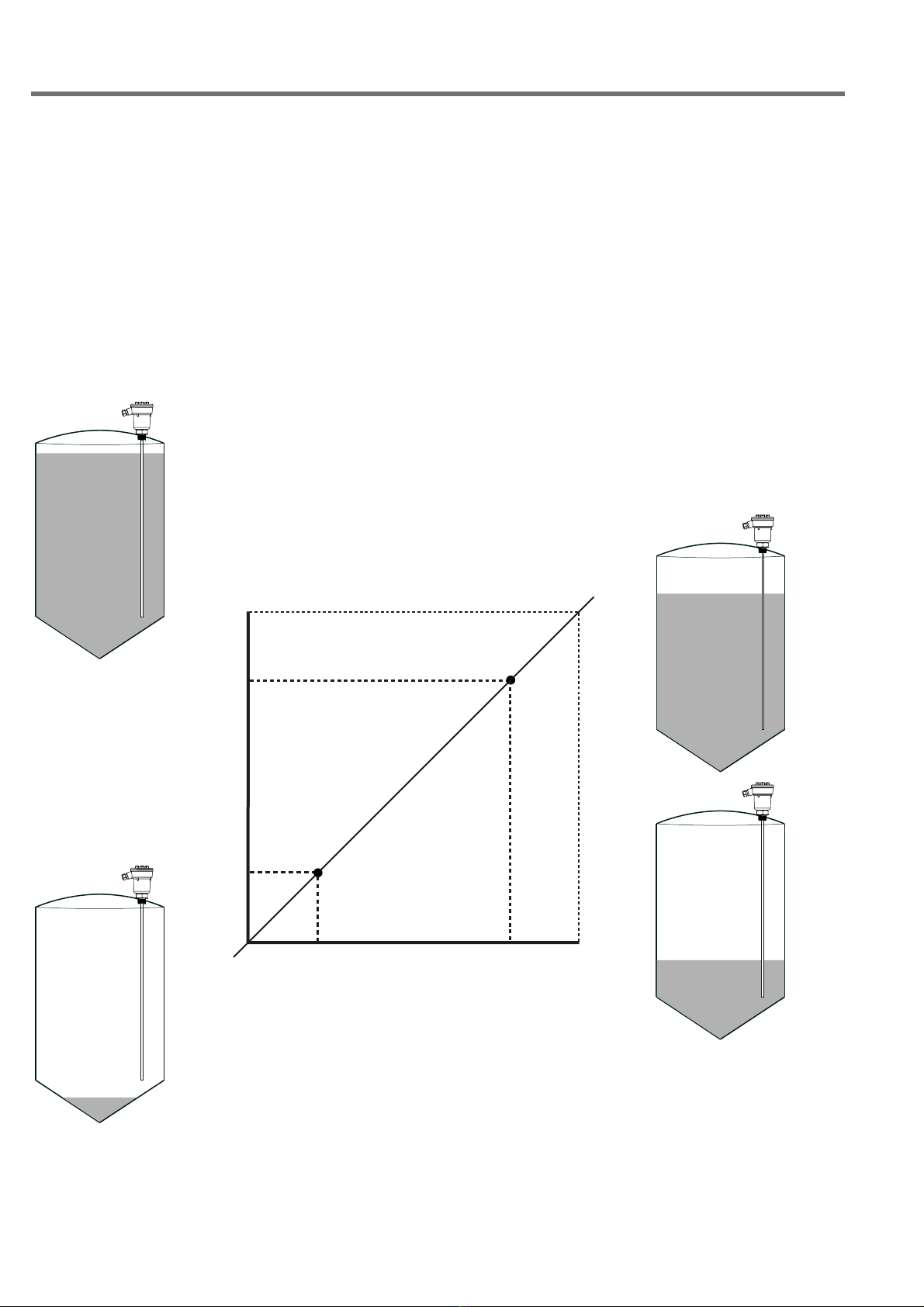
7.1 CALIBRATION
The TC22÷25 calibration can be made by means the P1 and P2 push-buttons in two different procedures:
a) Full-Empty Calibration.
b) High and Low-point Calibration.
To calibrate, needs to lodge the “TC22÷25” into the head connection of the capacitance sensor installed into the vessel
or tank in which needs the level measurement. Depends to the possibility to reach easily 0% and 100% level is pos-
sible to use: “Full-Empty Calibration” or, when 0% and 100% level can’t be reached “High and Low-point Calibration”
procedure can be used, see fig.below.
Important!
The calibration can be done first with empty and than with full (as the above procedure) or first with full and than with
empty as well.
TC22÷25 - calibration
4mA 20mA
0%
100%
empty
full
high
point
low
point
level
full
100% 20mA
empty
0% 4mA
intermediate points
calibration
high
point
low
point
Ce manuel convient aux modèles suivants
3
Table des matières


