User Guide : 900 Series Wireless Headsets: Second Generation 4
SetcomCorp.com | Main: 1-650-965-8020 | Fax: 1-650-965-1193
2.5 Pairing
Your headset is shipped pre-paired to its Base Station.
If you need to re-pair your headset to its Base Station or pair it to another Base Station, follow
these steps:
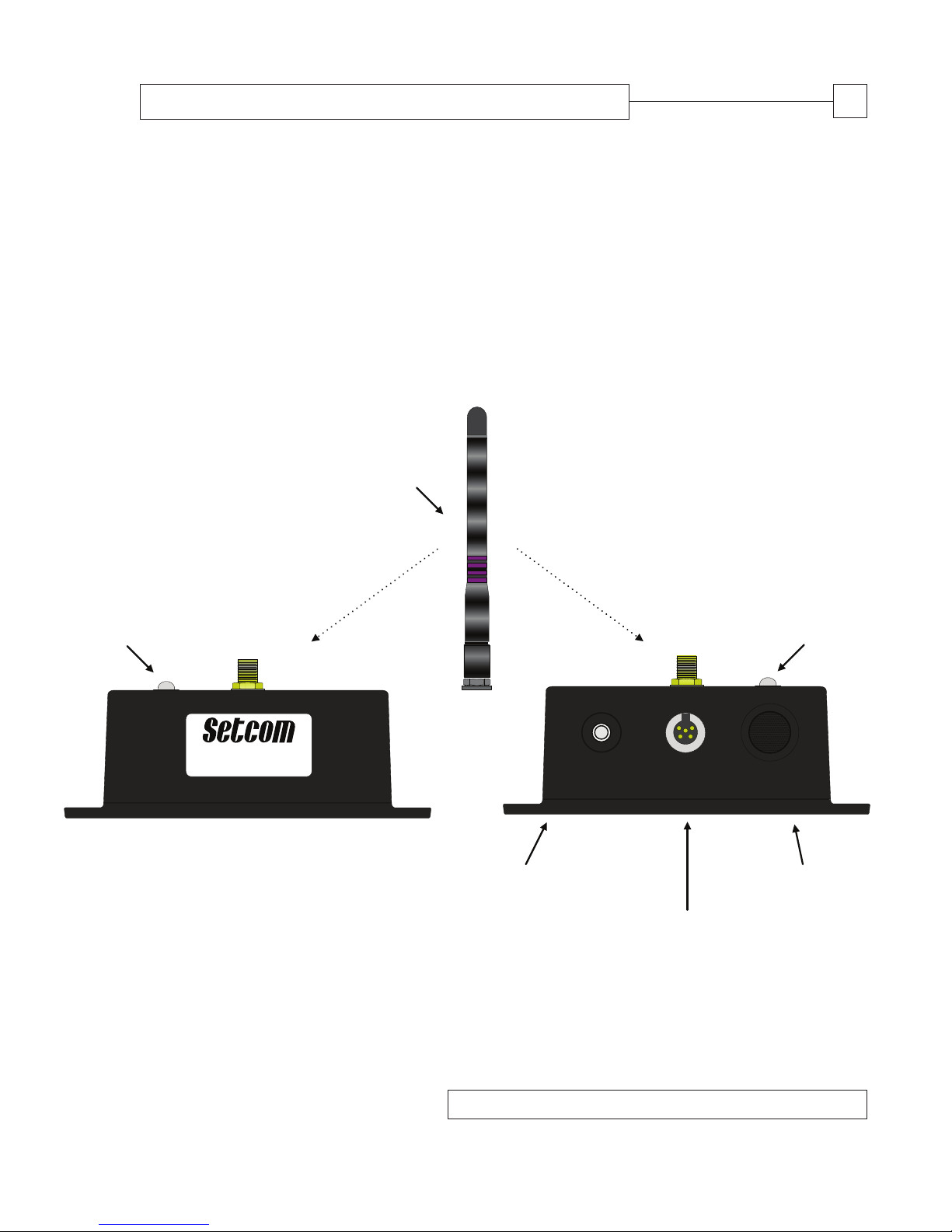
- Verify that the Base Station is turned on. When the Base Station is on, its LED Indicator
(Fig. 2 [a]) will show a steady green color.
- Turn on headset (see 2.2 above).
- If you have connected a Portable Radio Interface Cable (PRAC; see 2.4 above), disconnect it.
- Press and hold the Base Station’s Pairing Button (Fig. 2 [b]) for six seconds. The Base
Station’s LED Indicator (Fig. 2 [a]) will flash amber.
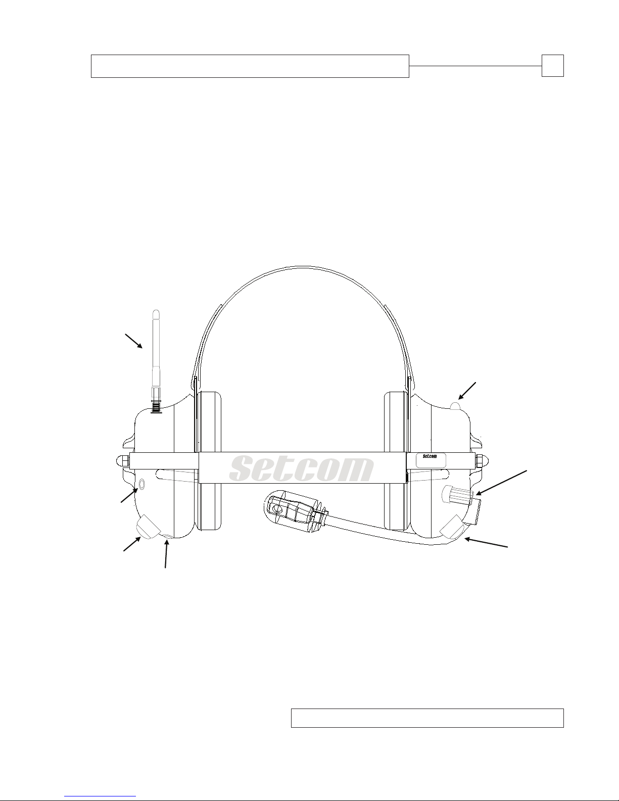
- Press and hold the headset’s Portable Radio Push-to-Talk (Fig. 1 [f]). Immediately after
(within no more than seconds), press and hold the headset’s Mobile Radio Push-to-Talk
(Fig. 1 [d]).
- Within two-to-three seconds, the headset will give one low “beep” and its LED Indicator
(Fig. 1 [b]) will begin flashing amber.
- After about 15 seconds, the Base Station and headset will “recognize” each other.
The headset will give one low beep followed by three high beeps. About five seconds later
the headset will beep three times, low to high, indicating its link with the Base Station has
been made. Both the headset and the Base Station’s LED Indicators will slowly flash green.
2.6 Headset LED Indicator (Fig. 1 [b])
•Steady green: Power is on and the headset is idle (not linked).
•Slow flashing green: Power is on, and the headset is linked to the Base Station.
•Very slow flashing green: The headset has gone into sleep mode.
•Steady amber: The headset is charging and turned off. The LED turns off when
the headset is fully charged.
•Steady yellow: The headset is charging and turned on. The LED goes steady green
when the headset is fully charged.
•Amber with green flashes: The headset is turned on, linked to the Base Station and charging.
•Fast flashing amber: The headset is in pairing mode and seeking a link with the
Base Station.
3.0 BASE STATION OPERATION
3.1 Installing the Base Station
•Mount the Base Station in an enclosed area away from direct exposure to the elements using
the four mounting screws provided (part number: 21-8006). For optimal range, position the
Base Station as high as practically possible (e.g. on the roof of a vehicle’s cab, where the
Base Station is installed in a vehicle). In all cases, position the Base Station’s antenna
vertically (relative to the ground).