Sequoia SQ864 Guide rapide de l'utilisateur

SQ864
GPRS Terminal
Hardware reference manual
Rev 2.1.4
Sales: +44 (0) 118 967 9000
Fax: +44 (0) 118 976 9020
www.sequoia.co.uk

SQ864
GPRS Terminal
2
Sales: +44 (0) 118 967 9000
Fax: +44 (0) 118 976 9020
www.sequoia.co.uk
Rev 2.1.4 Jan 2011
Wireless Technology
Experience The Freedom
CONTENTS
Contents
1. Disclaimer
2. Introducon
3. Denions
4. Device States
5. Interfaces
5.1 Power Supply Requirements
5.1.1 Power Connector
5.2 I/O Interface
5.3 Digital Output
5.4 Digital Input
5.5 RS232
5.6 SIM Socket
5.7 Antenna
5.7.1 Antenna Placement
5.7.1 Antenna Connecon Cable
6. Power Consumpon
7. Switching the SQ864-GPRS Terminal ON and OFF
8. Dimensions
8.1 Top View
8.2 Serial Connector View
8.3 Antenna and Power View
8.4 Sim and GPIO Indicator View
9. Terminal Installaon Consideraons
10. How to Install the Terminal
10.1 Power Supply
10.2 Securing the Modem
11. Safety and Product Care
11.1 General Precauons
11.2 Simm Card Precauons
11.3 Antenna Precauons
12. Safet Recommendaons
13. Conformity Assessment
14. Revision History
SQ864
GPRS Terminal
3
Sales: +44 (0) 118 967 9000
Fax: +44 (0) 118 976 9020
www.sequoia.co.uk
Rev 2.1.4 Jan 2011
Wireless Technology
Experience The Freedom
3. Denions
Term Denion
USB Universal Serial Bus
VSWR Voltage Standing Wave Rao
SMA Sub Miniature version A
LED Light Eming Diode
ESD Electro-Stac Discharge
SQ864
GPRS Terminal
4
Sales: +44 (0) 118 967 9000
Fax: +44 (0) 118 976 9020
www.sequoia.co.uk
Rev 2.1.4 Jan 2011
Wireless Technology
Experience The Freedom
4. Device States
The current state of the device is indicated by the status LEDs as shown in Table 1 below.
Table 1 Device status LEDs
The current state of the device is indicated by the status LEDs as shown in Table 1 below.
Table 1 Device status LEDs
LED colour State
Red (STAT_LED)
Flash rate once per second: Net search / not registered / turning o
Slow rate once every 3 s: Registered full service
Constant ON: Ringing OR call in progress
OFF: Module power down
Green (TGPIO_01) Reserved / test only
Blue (TGPIO_02) Reserved / test only
Current Device State Input Next state Indicaon of new state
Power O Connect power Run Mode Red LED will ash once per
second
Run Mode Insert a valid SIM card On Network Red LED will ash once every 3
seconds
On Network Apply pulse to pin 3 of power
connector Power o No acvity on any LED
Run Mode Apply pulse to pin 3 of power
connector Power o No Acvity on any LED
SQ864
GPRS Terminal
5
Sales: +44 (0) 118 967 9000
Fax: +44 (0) 118 976 9020
www.sequoia.co.uk
Rev 2.1.4 Jan 2011
Wireless Technology
Experience The Freedom
5. Interfaces
• RJ12 6-way (power connector)
• 4 Input GPIO
• SIM card reader
• SMA male coaxial jack (antenna connector)
• Sub-D socket, 9 pin (RS232 serial port)
5.1 Power supply requirements
The DC power supply must be connected to the power input. The characteriscs of the power input are as follows :
• Input voltage 5 to 16V DC
• Nominal input voltage 12V DC
• Supply current
• Peak 2A
• Average standby 25mA
• Call in progress 250mA
• Ringing 250mA
The module is supplied with a 12V mains adaptor. It can also be powered from an alternave power source with a voltage range 5 to 16V,
2A peak current.
Input protecon :
• On board reverse polarity protecon
• Overvoltage spike protecon to 30V for 1mS.
• ESD protecon to +/-4KV contact discharge and +/-8KV air discharge.
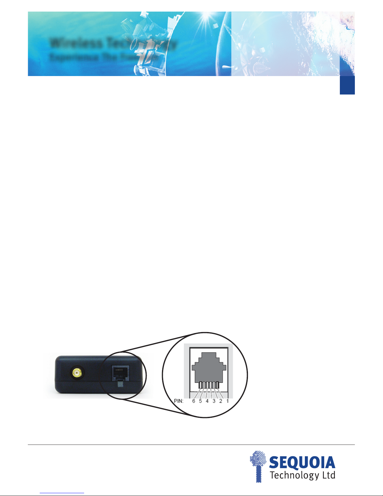
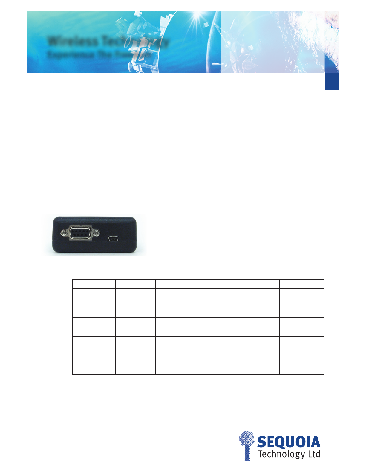
5.1.1 Power Connector
Figure 1 SQ864 Power Connector
The pin out and pin funcon of the power connector is shown in table 3.
SQ864
GPRS Terminal
6
Sales: +44 (0) 118 967 9000
Fax: +44 (0) 118 976 9020
www.sequoia.co.uk
Rev 2.1.4 Jan 2011
Wireless Technology
Experience The Freedom
Table 3 Power connector pin funcon
Table 4 Modem Power on state
Each pin of type Input is acvated when the voltage on the pin is in the range +2.1V to +16V DC. Pins of type I/O are acvated when the
voltage on the pin is in the range +2.1V to +12V DC. The minimum output drive voltage on pins type I/O is 2.2V
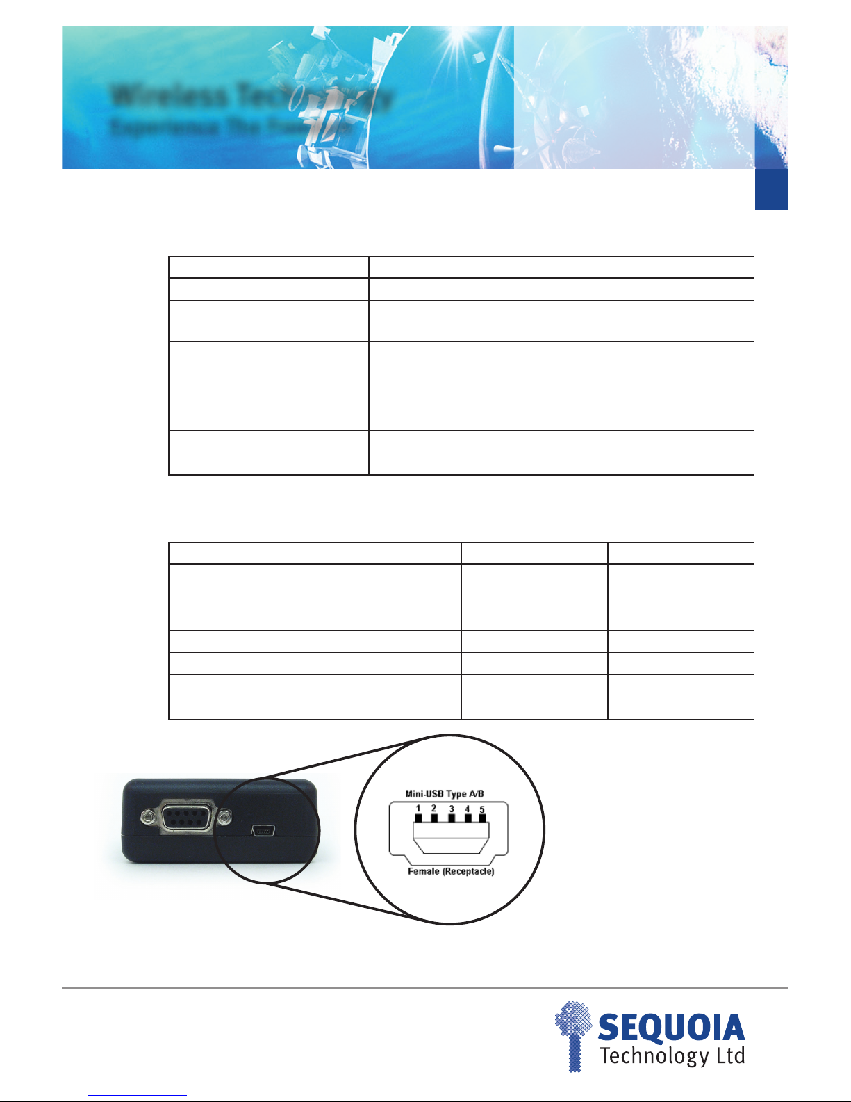
5.2 I/O Interface
A mini USB type B connector is provided for general purpose IO. ESD protecon to +/-4KV contact discharge and +/-8KV air discharge is
provided. Pins on this connector are available for control from the embedded applicaon as shown in table 5.
PIN number Part number Funcon
10V Common 0V connecon
2 RESET_IN External reset input. 0V to 0.5V, or open circuit inacve (Reset OFF), 2 to
16V acve (Reset ON), must be acve for at least 200ms then released.
3 POWER_OFF_IN External power O input, 0V to 0.5V, or open circuit inacve, 2 to 16V pulse
acve (no minimum duraon) (POWER OFF).
4 POWER_ON_IN
External power ON input, 0V to 0.5V, or open circuit inacve, 2 to 16V pulse
(no minimum duraon) acve (POWER ON). Not required for inial power
up, only if unit turned o with POWER_OFF_IN.
5 IGNITION_IN Oponal: Detecon of ignion on.
6POWER +VE 12V nominal, 5-16V DC, 2A peak, reverse polarity protected
Modem State Pin-4 (ON) Pin-3 (OFF) Modem ON/OFF
OFF ACTIVE ACTIVE OFF
ON ACTIVE ACTIVE ON
ON NOT-ACTIVE ACTIVE Switches OFF
OFF NOT-ACTIVE ACTIVE OFF
OFF ACTIVE NOT-ACTIVE Switches ON
ON ACTIVE NOT-ACTIVE ON
SQ864
GPRS Terminal
7
Sales: +44 (0) 118 967 9000
Fax: +44 (0) 118 976 9020
www.sequoia.co.uk
Rev 2.1.4 Jan 2011
Wireless Technology
Experience The Freedom
Table 5 Mini USB Connecons
The maximum/minimum input/output voltage allowed on the I/O pins is given in table 6
Table 6 GPIO minimum/maximum voltage
5.3 Digital Output
• Switch voltage is VIN high side switch
• Max output 400mA
• Short circuit protected
• ESD protected
• Under full control of embedded applicaon
The following command has to be used to inialise and to set the digital output:
AT#GPIO=5,1,1 switch output on
AT#GPIO=5,0,1 switch output o
Mini USB Pin Signal on Telit GC864-PY Module Voltage level Funcon
1 GPIO5 CMOS 2.6V GPIO
2 GPIO7 CMOS 2.6V GPIO
3 GPIO8 CMOS 2.6V GPIO
4GPIO11 CMOS 2.6V GPIO
5 GPIO12 CMOS 2.6V GPIO
CASE GND 0v GND
Signal Name Parameter Minimum Maximum
GPIO_05 Input high level 2.1V 5.5V
GPIO_07 to GPIO_12 Input high level 2.1V 3.3V
GPIO_05 to GPIO_12 Input low level 0V 0.5V
GPIO_05 to GPIO_12 Output high level 2.2V 3.0V
GPIO_05 to GPIO_12 Output low level 0V 0.5V
SQ864
GPRS Terminal
8
Sales: +44 (0) 118 967 9000
Fax: +44 (0) 118 976 9020
www.sequoia.co.uk
Rev 2.1.4 Jan 2011
Wireless Technology
Experience The Freedom
5.4 Digital Input
• Max voltage dened in Table 6
• Short circuit protected
• ESD protected
• Under full control of embedded applicaon
The following AT commands can be used to inialise and to read the status of the GPIO:
AT#GPIO=5,2,0 (read GPIO_5, PIN1 Mini USB)
AT#GPIO=7,2,0 (read GPIO_7, PIN2 Mini USB)
AT#GPIO=8,2,0 (read GPIO_8, PIN3 Mini USB)
AT#GPIO=11,2,0 (read GPIO_11, PIN4 Mini USB)
AT#GPIO=12,2,0 (read GPIO_12, PIN5 Mini USB)
5.5 Digital Input
A standard RS232 interface is provided through a 9 way D-type socket.
All RS232 pins provide the following ESD protecon:
• +/-15kV – Human Body Model
• +/- 8kV – IEC61000-4-2, Contact Discharge
• +/-15kV- IEC61000-4-2, Air Gap Discharge
As a minimum, TXD, RXD and 0V are required to set up serial communicaons with the module.
Pin Number Signal Direcon Descripon Voltage Level
1DCD Output Data Carrier Detect +/- 5.4V
2RXD Output Received data +/- 5.4V
3TXD Input Transmit data +/- 25V
4DTR Input Data terminal ready +/- 25V
50V GND Ground 0V
6 DSR Output Data set ready +/- 5.4V
7RTS Input Request to send +/- 25V
8CTS Output Clear to send +/- 5.4V
9RI Output Ring Indicator +/- 5.4V
SQ864
GPRS Terminal
9
Sales: +44 (0) 118 967 9000
Fax: +44 (0) 118 976 9020
www.sequoia.co.uk
Rev 2.1.4 Jan 2011
Wireless Technology
Experience The Freedom
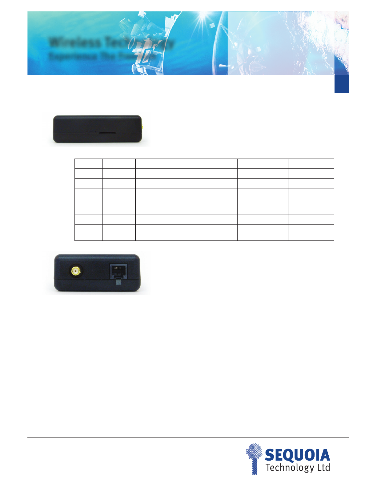
5.6 SIM Socket
A standard SIM socket is provided which accept 1.8V/3V SIM card for carrier subscripon.
5.6 SIM Socket
A SMA connector is provides to allow connecon of a passive or acve antenna. For opmum performance the antenna assembly
connected to this device is required to have the following characteriscs:
• Specied designed operaon in the following bands :
• GSM 850/900 MHz
• GSM 1800./1900 MHz
• The characterisc impedance on any antenna or cable assembly aached to this device should be 50R
• The antenna must be capable of handling a minimum of 2W output power
• The VSWR should be less than 3:1 to avoid damage to the device.
5.7.1 Antenna placement
When in service the antenna should be placed away from electronic devices or other antennas. The recommended minimum distance
between adjacent antennas, operang on a similar radio band, is at least 50cm.
5.7.2 Antenna connecon cable
If a cable is used to connect the device to the antenna this cable must be a high quality low loss cable. The cable and any connectors used
should have 50R impedance.
Pin No. Name Usage Descripon Voltage Level
1SIM_VCC Power supply for the SIM Data Carrier Detect +/- 5.4V
2 SIM_RESET Output – Resets the SIM Received data +/- 5.4V
3SIM_CLOCK Output – Clock signal for clocking data I/O
from the SIM Transmit data +/- 25V
5,10 SIM_GND 0V Data terminal ready +/- 25V
7 SIM_IO Data I/O signal for the SIM Request to send +/- 25V
9SIM_IN Input – Detects the presence of SIM card in
the connector Clear to send +/- 5.4V

SQ864
GPRS Terminal
10
Sales: +44 (0) 118 967 9000
Fax: +44 (0) 118 976 9020
www.sequoia.co.uk
Rev 2.1.4 Jan 2011
Wireless Technology
Experience The Freedom
6. Power Consumpon
The measurement was taken with 2 Voltages (5 V, 12V).
The terminal was connected via RS232 to a PC in order to send/
receive AT commands. The temperature was maintained in a
temperature chamber. The voice call with Power level 5 in GSM
900 was established with a GSM Tester.
SQ864-GPRS 5V 12V
Terminal switched o 0.01 mA 0.67 mA
On, network connecon (Idle mode) 71 mA 29 mA
On, network connecon voice call (power level 5) GSM 900
235 mA 98 mA
7. Switching the SQ864-GPRS Terminal ON and OFF
The SQ864-GPRS automacally switches on when power is applied
to the terminal . If the unit is then powered o the are two ways to
switch the modem back on again.
• Either assert TO_IN high (1s < t < 2s)
• Acvate the RS232 control line DTR, high for > 0.2s
The modem is fully operaonal aer 4 seconds. Logging onto the
GSM network may take longer than this and is outside the control
of the modem and is network and frequency dependant. The
modem can is congured to automacally turn on at power up.
Once the modem is switched o a posive signal connected to
TO_IN (pin 4) will switch on the modem.
In this case DTR must be used to switch the modem on again aer
it has been switched o or reset, while power is sll applied.
NOTE: DTR must be cycled from low to high.
NOTE: The TO_IN signal requires a posive “edge” (a “sharp” signal
transion from low to high) to turn the modem on. This transion
should be a rising signal from 0V (GND) to VCC, or at least a large
fracon of that voltage range. Very slow transions (signicantly
slower than many milliseconds) or very small transions (e.g. only
a few volts instead of 0V to VCC) will not turn on the module (since
they are not considered to be a “posive edge”).
Although this will not be an issue in almost all typical applicaons
of the modem, under the following condion special design care
has to be taken:
• Large capacitors in your power supply which will lead to
slow leading and falling edges
• Slow analogue signals used to assert TO_IN
Both cases above might prevent the modem from recognizing
the power-up signal this is no failure of the modem itself, the
same would apply to almost any electronic device that provides a
separate “power-on” or “reset” signal.
If you are in doubt, please use the following recommendaons:
• Use Vcc power signal from the AC adapter that is
provided with your unit and is known to work properly
with your modem
• Make sure that your signal and system design adheres to
the recommendaons above
• Consult our support team that will be more than happy
to assist you.
There are three ways to switch o the modem:
• Use the AT#SHDN command
• HR_IN (1s < t < 2s)
• DTR permanently to GND
A delay of up to 10s can be expected for the unit to power o as
the modem logs o the GSM network.
A full system reset, independent of the status of the soware, may
be applied to the modem by applying a 2 to 16V acve pulse to pin
2 of the RJ12 power connector (RESET_IN). Signal must be acve
for at least 200ms then released.
Table des matières


