
Seiwa BB 50 Manuel utilisateur

User Manual
Copyright 2005 Seiwa - Hong Kong
All rights reserved. Printed in Italy. No part of this publication may be reproduced or distributed in any form or by any
means, or stored in a database or retrieval system, without prior written permission of the publisher.
BB 50/200
Dual Frequency 50 & 200kHz Black Box Fish Finder
CODE: A-160205

4User Manual
Contents
Important Information ................................................................................. 6
CAUTION ................................................................................. 6
About this User Manual ................................................................................. 7
INTRODUCTION ................................................................................. 7
CONVENTIONS USED ................................................................................. 7
HOW THIS USER MANUAL IS ORGANIZED ............................................................... 8
IF YOU NEED ASSISTANCE ................................................................................. 8
1. Overview ................................................................................. 9
1.1 FISH FINDER ................................................................................. 9
Features & Functions ................................................................................. 9
1.2 Selecting the Fish Finder port ........................................................................ 10
2. Fish Finder ............................................................................... 11
2.1 UNDERSTANDING THE FISH FINDER PAGE ..................................................... 11
2.1.1 Understanding the Echogram display ................................................... 12
2.2 DISPLAYING THE FISH FINDER PAGE ............................................................. 13
2.2.1 How to select the Fish Finder page ....................................................... 13
2.2.1.1 Selection by Soft Key ............................................................ 14
2.2.2 Fish Finder Full page .......................................................................... 15
2.2.3 Dual Frequency page ......................................................................... 16
2.2.4 Zoom page ............................................................................... 16
2.2.5 Chart/Fish page ............................................................................... 17
2.3 ZOOM MODES ............................................................................... 18
2.3.1 The Bottom Lock Zoom ...................................................................... 18
2.3.2 The Marker Zoom .............................................................................. 18
2.4 SOUNDER ADJUSTMENTS WITH SOFT KEYS .................................................... 18
2.5 INFO ON FISH FINDER: SYSTEM INFORMATION ............................................... 19
2.5.1 The System Update menu .................................................................. 19
3. Setup your Fish Finder ............................................................................... 21
3.1 FISH FINDER SETUP MENU ........................................................................... 21
3.1.1 Preset Mode ............................................................................... 21
3.1.2 Gain Mode ............................................................................... 21
3.1.3 Range Mode ............................................................................... 21
3.1.4 Depth Mode ............................................................................... 22
3.1.5 Bottom Range ............................................................................... 22
3.1.6 Depth ............................................................................... 22
3.1.7 Shift ............................................................................... 22
3.1.8 Scroll Speed ............................................................................... 22
3.1.9 White Line ............................................................................... 22
3.1.10 Interference Rejection ....................................................................... 22
3.1.11 Frequency ............................................................................... 22
3.1.12 Sensitivity ............................................................................... 22
3.1.12.1 Frequency ........................................................................... 23
3.1.12.2 Gain ............................................................................... 23
3.1.12.3 Noise Tresohold .................................................................... 23
3.1.12.4 STC ............................................................................... 23
3.1.13 Fish Symbol ............................................................................... 23
3.1.14 Color Settings ONLY FOR COLOR CHART PLOTTER .................................. 23
3.1.15 Transducer Setup .............................................................................. 24

5
User Manual
3.1.15.1 Keel Offset ........................................................................... 24
3.1.15.2 Calibrate Sound Speed .......................................................... 24
3.1.15.3 Calibrate Water Speed ........................................................... 24
3.1.15.4 Calibrate Water Temperature .................................................. 24
3.1.15.5 Calibrate Aux Temperature ..................................................... 24
3.1.16 Alarms ............................................................................... 24
3.1.16.1 Shallow Water ...................................................................... 24
3.1.16.2 Depth Water ........................................................................ 25
3.1.16.3 Temperature Upper ............................................................... 25
3.1.16.4 Temperature Lower ............................................................... 25
3.1.16.5 Temperature Rate ................................................................. 25
3.1.16.6 Fish Alarm ........................................................................... 25
4. BB 50/200 ............................................................................... 27
4.1 TECHNICAL SPECIFICATIONS ....................................................................... 27
4.2 DIMENSIONS ............................................................................... 28
4.3 MOUNTING THE FISH FINDER ....................................................................... 28
4.3.1 Installation ............................................................................... 28
4.3.2 Installing Optional Devices ................................................................. 29
4.4 STATUS LED ............................................................................... 29
4.5 EXTERNAL CONNECTIONS ............................................................................ 31
4.6 POWER SUPPLY WIRING DIAGRAM ................................................................ 32
4.7 PLOTTER CONNECTION DIAGRAM .................................................................. 32
5. Transducers ............................................................................... 35
6. Frequently Asked Questions ............................................................................ 37
Analytical Index ............................................................................... 41

6User Manual
Important Information
CAUTION
♦Please read through this manual before the first operation. If you have any
questions, please contact the Company's customer service or your local
dealer.
♦The BB 50/200 is not built water proof. Please make sure to avoid water
intrusion into the unit. Water damage is not covered by the warranty.
♦Extensive exposure to heat may result in damage to the BB 50/200.
♦Connection to the power source with reversed polarity will damage the BB
50/200 severely. This damage is not covered by the warranty.
♦The BB 50/200 contains dangerous high voltage circuits which only experi-
enced technicians MUST handle.
NOTE We will not be liable for errors contained herein, or for incidental or
consequential damages in connection with the performance or use of this
material.

7
User Manual
About this User Manual
INTRODUCTION
The chart plotter combined with the sonar performance of the Fish Finder is one of
the most advanced marine navigation system available.
Please read carefully this User Manual to learn the operating features for your unit.
Refer to your chart plotter User Manual for all other unit operating instructions.
CONVENTIONS USED
Throughout this User Manual, the labelled keys are shown in capital letters en-
closed in square brackets, for example [ENTER]; the software keys are shown in
small capital letters enclosed in square brackets, for example [EDIT].
Menu operations are in bold characters listed by keys sequence with the menu
names enclosed between inverted commas, for example [MENU] + "ALARMS"
+ [ENTER] means: press the [MENU] key, using the cursor key select the Alarms
menu and then press [ENTER].
Any menu operation and function activation in this User Manual is related to 5.7,
8 and K chart plotter LCD models (see the following table). Whenever it is neces-
sary, a note has been inserted for 10.4 and 12.1 LCD models.
CHART PLOTTER NAME DESCRIPTION SOFTWARE LCD
MURENA 5.6" Sunlight Readable Color Display S3egSW7vc 5.7
External Smart GPS Receiver
MURENA iGPS 5.6" Sunlight Readable Color Display S3igSW7vc
Internal GPS Receiver
TIGERSHARK Plus 5.6" Gray Levels Display S3egSW7m
External Smart GPS Receiver
MILLENNIUM 7 5.6" Gray Levels Display S3igSW7m
Internal GPS Receiver
NAUTILUS iGPS Plus 5.6" Sunlight Readable Color Display S3egSW7c
External GPS Receiver
MILLENNIUM 7 Color 5.6" Sunlight Readable Color Display S3igSW7c
Internal GPS Receiver
BARRACUDA 7" Sunlight Readable Color Display S3egSW7wc 8
External Smart GPS Receiver
BARRACUDA iGPS 7" Sunlight Readable Color Display S3igSW7wc
Internal GPS Receiver
EXPLORER MK-II Plus Controller for Color Display XSegSWctcj K
External Smart GPS Receiver
BARRAMUNDI 11" Color Display XSegSW11c 10.4
External Smart GPS Receiver & Video Input
BARRAMUNDI Plus 11" Sunlight Readable Color Display XSegSW11c
External Smart GPS Receiver & Video Input

8User Manual
SEAWAVE 12 MK II * 12" Color Display XSegSW12c 12.1
External Smart GPS Receiver
NOTE* To connect the SEAWAVE 12 MK II below s/n 4129999 please contact your
local dealer (to make the hardware change necessary).
HOW THIS USER MANUAL IS ORGANIZED
♦CHAPTER 1: Overview
Introduction to the basic information on the Fish Finder, its features
and use.
♦CHAPTER 2: Fish Finder
Helps you understand how the chart plotter is connected to the Fish
Finder and how to operate to improve your fishing.
♦♦
♦♦
♦CHAPTER 3: Setup your Fish Finder
Description of the Fish Finder Setup menu.
♦♦
♦♦
♦CHAPTER 4: BB 50/200
Technical specification, dimension and installation of the BB 50/200
and set up of the hardware configuration.
♦♦
♦♦
♦CHAPTER 5: Transducers
Introduction to the basic information on the transducer (device that
transmits and receives sound waves into the water).
♦♦
♦♦
♦CHAPTER 6: Frequently Asked Questions
The Analytical index is at the end of this User Manual.
IF YOU NEED ASSISTANCE
If your chart plotter does not operate properly, please refer to the chart plotter
User Manual.
9
User Manual
1. Overview
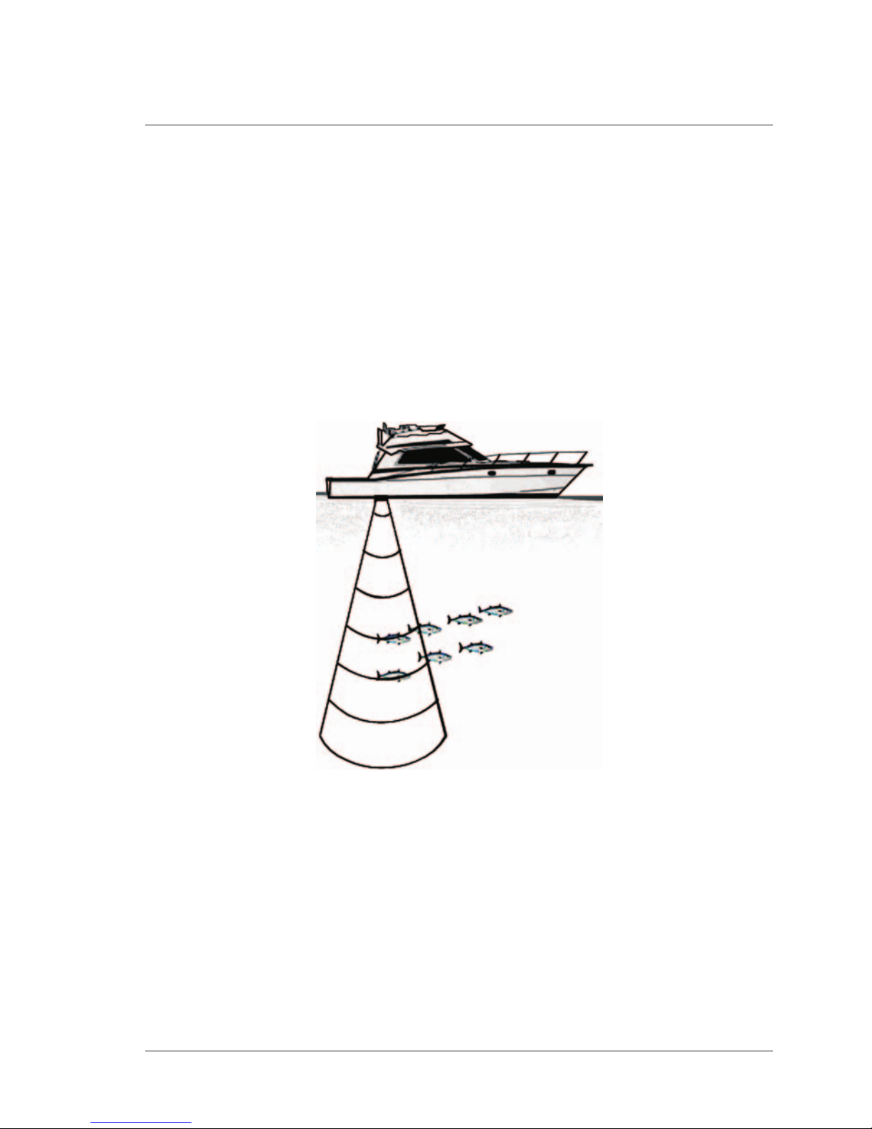
The Fish Finder consists of a high power transmitter, sensitive receiver and a
transducer. The Fish Finder sends an electrical pulse to the transducer which
contains an element that converts the pulse into acoustic (sound) wave which is
sent through the water. As this wave travels from the transducer to the bottom, it
may strike fish, structures, thermal clines (temperature changes in the water).
When the wave strikes an object(s) a certain amount of the wave is reflected back
to the transducer depending on the composition and shape of the object. When
the reflected wave is returned to the transducer it is converted into an voltage
and is amplified by the receiver, processed and sent to the display. The speed of
sound in water is roughly 4800 ft./sec, so the time lapse between the transmitted
signal and the received echo can be measured and the distance to the object
determined.
Fig. 1 - Fish Finder working principle
1.1 FISH FINDER
Features & Functions
♦A-Scope (displays Sonar Echo in real time)
♦2X and 4X Zoom (capability to magnify any part of the Echogram image
of a fixed rate)
♦Full auto to manual, working preset modes (Fish, Cruise, Autorange,
Bottom Lock, Manual)
♦Bottom Lock (capability to magnify a user defined range around the
bottom)

10 User Manual
♦White Line (help distinguish between fish and bottom, when fish is swim-
ming close to the bottom)
♦STC (allows reducing or eliminating the surface clutter)
♦Interference Rejection (allows reducing interference from other boats/
Fish Finders)
♦Noise Filter
♦Fish Symbol feature (*)
♦Automatically Transducer Setup. Recognition for devices (automatic
trasducer identification and parameters setup for best performance)
♦Alarms Handling (Shallow Alarm, Depth Alarm, Fish alarm, Tempera-
ture Upper, Temperature Lower)
NOTE* On specific software version available.
1.2 SELECTING THE FISH FINDER PORT
If the Fish Finder is connected to the Port 3 (see Par. 4.7), follow the procedure:
[MENU] + [MENU] + "ADVANCED" + [ENTER] + "Input/Output" + [ENTER]
+ "Port 3 Input" + [ENTER]+ "BBFF 50/200" + [ENTER]
This is the default setting if the connecting cable supplied with the Fish Finder is
used.
If the Fish Finder is connected to the Port 2 (see Par. 4.7), follow the procedure:
[MENU] + [MENU] + "ADVANCED" + [ENTER] + "Input/Output" + [ENTER]
+ "Port 2 Input" + [ENTER] + "BBFF 50/200" + [ENTER]

11
User Manual
2. Fish Finder
This chapter is intended to help you understand how the chart plotter with the
Fish Finder connected operates to improve your fishing.
2.1 UNDERSTANDING THE FISH FINDER PAGE
The display on chart plotters shows a history of time of the echoes received by
the transducer. The chart plotters have a menu that allows adjustments to re-
ceiver sensitivity, depth range and scrolling speed of the Fish Finder display.
Fig. 2.1 - The Fish Finder page
The following is a short description of terms listed in the previous Fig. 2.1:
Warning Message
Flashing label "Simulation" when the echo sounder is in Simulation mode.
Echogram window
Graphic presentation of sonar soundings recorded as a continuous profile
scrolling across the screen from right to left. Such recordings represent the
image of the water beneath your boat, items appear as they pass under your
transducer; the items on the right side of the screen are closer to you than
those on the left. The correct interpretation of the Echogram allows retrieving
useful information about what is under the boat. See the following Par. 2.1.1
for more information.
Color Bar
Colored scale located on the left side of the screen that shows the colors used
in the Echogram to represent the echoes strength. The color on the top of the
bar represents the maximum sonar strength, while the color on the bottom of
the bar represents the minimum sonar strength.
12 User Manual
Digital Depth
Readout of the current bottom depth.
Water Temperature
Readout of the current water temperature returned by the TEMP 1 sensor
included into specific transducers.
Alarm Bar
Bars showing the shallow water and deep water alarm values. The alarm is
triggered when depth is outside the range.
Depth ruler
Vertical graduated bar. It is a scale which reflects the depth of the area being
displayed.
Variable Depth Marker (VDM)
Horizontal line on to the Echogram window with a depth label. The up/down
cursor keys can move it up and down. The label displays the depth of the
cursor position. It can be moved to any location pinpointing the depth of a
target.
Zoom Bar
Bar showing the portion of the Echogram currently represented in the zoomed
window (on the left part of the screen). It is turned on selecting Zoom Full
display page.
A-Scope
A real time representation of fish and bottom features passing through the
beam of the transducer. It is drawn as horizontal lines whose length and hue
is proportional to the sonar strength returned. When the default palette is
selected, the strongest sonar returns will be shown as the color displayed of
the top of Color Bar while the weakest as the bottom color.
Operating Frequency
Readout of the selected operating frequency.
2.1.1 Understanding the Echogram display
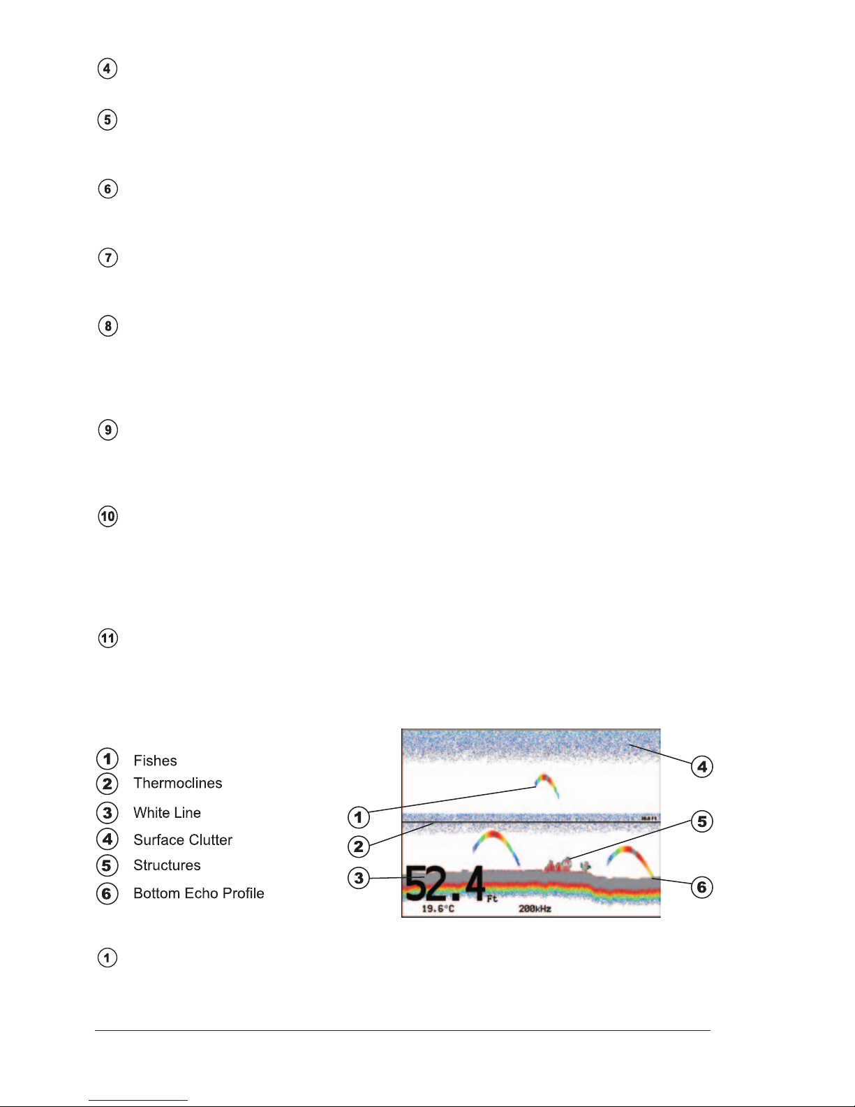
The main elements that can be easily distinguished into an Echogram are:
Fig. 2.1.1 - The Fish Finder Echogram
Fishes
Fishes are represented as arcs because of the cone angle of the transducer.
Ce manuel convient aux modèles suivants
1
Table des matières
Autres manuels Seiwa Sondeur de pêche


