SEELEY INTERNATIONAL Multi-Magic Manuel utilisateur

USER MANUAL
MULTI-MAGIC WALL CONTROLLER
®
Original English Instructions
ILL2468-A


MULTI-MAGIC WALL CONTROLLER USER MANUAL 859731-E |1
TABLE OF CONTENTS
OVERVIEW 2
COOLER MODELS 2
KIT CONTENTS 2
SPECIFICATIONS 2
QUICK START 3
24Vdc POWER AND RS 485 MODBUS COMMUNICATIONS WIRING 3
MAIN SCREEN LAYOUT 4
RS 485 MODBUS NETWORK SETUP - FIRST TIME USE 4
PHYSICAL DESCRIPTION & MOUNTING 5
WALL CONTROLLER INSTALLATION INSTRUCTIONS 6
CONNECTING 7
COMMUNICATION CABLE SPECIFICATION 7
WIRING REQUIREMENTS 7
POWER 8
TERMINATING RESISTOR 9
OPERATION SCREENS 10
MAIN MENU 10
COOL MODE (MANUAL SPEED CONTROL) 11
COOL MODE (AUTOMATIC SPEED CONTROL) 12
VENT MODE 13
PROGRAM MODE 14
EDIT THE 7-DAY PROGRAM 15
SETTING SCREENS 16
MENU 16
TIME AND DATE 17
LANGUAGE 17
SECURITY LOCK 18
TEMPERATURE UNITS 18
CONFIGURATION SCREENS 19
MENU 19
AUTO-RESTART 19
ROOM SENSORS 19
AMBIENT SENSORS 19
MINIMUM - MAXIMUM FAN SPEED LIMITS 20
MODBUS RS 485 NETWORK SETUP 21
DEVICE MONITOR SCREENS 22
MENU 22
COOLER MONITOR 23
FAULT HISTORY 23
COOLER FAULTS AND TROUBLESHOOTING 25
FAULT SCREEN DISPLAY 25
FAULT CODE DESCRIPTIONS 26
OTHER POTENTIAL PROBLEMS 27
APPENDIX - EXAMPLE WIRING SCHEMATIC 28

2 |859731-E
OVERVIEW
COOLER MODELS
The Wall Controller is compatible with CW-H and CW-80 coolers with Multi-Magic controls
These instructions are to be read in conjunction with the Installation and Operation and
Maintenance literature supplied with the coolers.
KIT CONTENTS
SPECIFICATIONS
General
Power supply 24 V AC/DC +/-10 %
Power consumption 3.2 VA 1.3 W max
Degree of Protection IP20
Mounting Vertical Wall, Surface Mount
Ambient operating Temperature 0 to 50 oC (32 to 122 oF)
Ambient operating humidity (non-condensing) 0 to 75%
Ambient storage temperature -30 to 50 oC (-22 to 122 oF)
Ambient storage humidity (non-condensing) 0 to 75%
Embedded Temperature Sensor Characteristics
Type 10 k NTC type 2 thermistor
Resolution +/- 0.1 oC (+/- 0.2 oF)
Measurement range -40 to +50 oC (-40 to +122 oF)
Accuracy +/- 0.5 oC (+/- 0.9 oF) at 21 oC (70 oF)
typical calibration
Embedded Humidity Sensors Characteristics
Type and calibration Single point calibrated bulk polymer
Precision Reading range from 10 to 90% R.H. non-condensing
10 to 20 % precision: 10%
20 to 80 % precision: 5%
80 to 90 % precision: 10%
Stability Less than 1.0% yearly (typical drift)
Communication
Type RS 485 Modbus Client
Maximum of number of Modbus Server devices 15
ITEM IMAGE ITEM IMAGE
Multi-Magic
Wall Controller
Isolating Screw
MODBUS 120Ω
Terminating
Resistor
Instructions
ITEM 1 ITEM 2
ILL2425-A

MULTI-MAGIC WALL CONTROLLER USER MANUAL 859731-E |3
24 V AC/DC POWER AND RS 485 MODBUS COMMUNICATIONS WIRING
120
Ω
ILL3630-B
RS 485 -
RS 485 +
GND
-
ILL3630-B
QUICK START
WALL CONTROLLER
CW-H COOLER
ILL3879-AILL3631-E
CW-80 COOLER

4 |859731-E
ILL3632-A
INTERNAL
TEMPERATURE /
HUMIDITY
TIME
ON - OFF
COOL MODE
VENT MODE
PROGRAM MODE
SETTINGS
DATE
MAIN SCREEN LAYOUT
ILL3632-B
RS 485 MODBUS NETWORK SETUP - FIRST TIME USE
IMPORTANT - The Multi-Magic Wall Controller can control up to 15 CW-H and/or CW-80 coolers.
Ensure each cooler is powered up and has a unique node address set. Refer to installation
literature provided with the cooler for setup instructions.
Enter SETTINGS – CONFIGURATION – NETWORK menu
ILL3633-D
List shows all detected coolers.
Press EDIT to scan network and detect coolers.
Press SAVE to commit detected coolers to Wall Controller memory.
QUICK START
DATE TIME
ON OFF
COOL MODE
VENT MODE INTERNAL
TEMPERATURE /
HUMIDITY
PROGRAM MODE
SETTINGS
EDIT SAVE

MULTI-MAGIC WALL CONTROLLER USER MANUAL 859731-E |5
ILL3672-A
Number Description
1Colour touchscreen
2Power supply connector
3RS 485 Modbus connector
4Holes for temperature and humidity measurement
The Multi-Magic Wall Controller should be placed indoors, approximately 1.5 metres (5’) above the
oor, in the same zone in which cooling is required. Placement is critical for correct functioning of
the temperature and humidity sensors inside the Controller.
The following points must be taken into consideration:
• Avoid direct sunlight exposure.
• Avoid mounting on external walls.
• Avoid mounting the wall controller near heat sources such as stoves and televisions.
• Do not locate in the direct airow of the duct outlets.
• Do not locate in strong drafts or in dead spots such as cupboards/drawers.
• Always seal the wall cable entry hole.
• Avoid blocking or restricting the vent holes located on the underside of the Wall Controller, as
this is where the sensors are located. Important! Drafts within the wall cavity can impact the
temperature and humidity reading of the wall control. We recommend that the cable access
hole be sealed, but in such a way that the cable can still retreat into the wall cavity.
• The Wall Controller shall be mounted vertically.
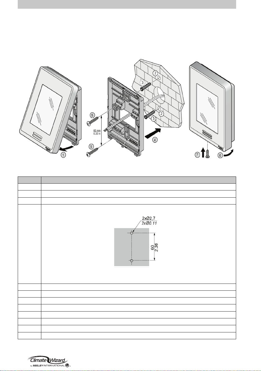
PHYSICAL DESCRIPTION & MOUNTING
WALL CONTROLLER DIMENSIONS AND SETUP NOTES
ILL3672-A
1
2
3
44
6 |859731-E
ILL3670-A
Step Action
1 Open unit by pulling on bottom side of the display (1)
2 Ensure correct side of base faces up
3 Pull cables 150 mm (5.90 in.) out from wall
4 Align base and mark location of two mounting holes on wall or panel (2)
CAUTION!
Always make sure there are no electrical cables, gas or water pipes, or the like, behind
where you intend to drill.
5 Install anchors (NOT INCLUDED) in wall (3)
6 Insert cable in central hole of base
7 Place rear cover on the wall and align it with mounting holes (4)
8 Insert screws (NOT INCLUDED) in mounting holes on each side of base (5)
9 Insert POWER and CONTROL wiring according to wiring chart
10 Gently push excess wiring back into hole
11 Gently align cover to top of base and snap in place from bottom (6)
12 Install the isolated screw connection for securing the plastic housing (7)
PHYSICAL DESCRIPTION & MOUNTING
WALL CONTROLLER INSTALLATION INSTRUCTIONS
ILL3671-A
ILL3670-A

MULTI-MAGIC WALL CONTROLLER USER MANUAL 859731-E |7
ILL3669-A
CONNECTING
C
mm2
mm2
AWG
AWG
7
7
0.28
0.28
mm
mm
0.2...2.5
24...14 24...14 22...14
0.5...0.6
4.42...5.31
22...14 2x 24...18 2x 24...16
2x 22...18 2x 20...16
0.2...2.5 0.25...2.5 0.25...2.5 2x 0.2...1 2x 0.2...1.5
2x 0.25...1 2x 0.5...1.5
in.
in.
N/m
Ø3.5mm (0.14in)
lb/in
COMMUNICATION CABLE SPECIFICATION
• Suitable for Modbus RS 485 applications
• Minimum 1 twisted pair (TP) and a third conductor
• Copper Conductors
• 0.5 mm2/ AWG 20
• Braided Shield with Drain Wire
• Characteristic impedance 120Ω
• Nominal capacity between conductors 89 pF/m
• Nominal capacity between conductors and shielding 161 pF/m
Use the twisted pair for the ‘+’ and ‘-‘ signal terminals. Use the 3rd conductor for the signal GND
terminals. Attach the braided shield / drain wire to the EARTH terminal at one end only.
ILL3705-A
ILL3705-A
WIRING REQUIREMENTS
• Communication wiring must be kept separate from AC power wiring.
• Always route communication cables at least 300mm (12”) away from high voltage cables and
high-power machines.
• Crossover high power cables at right angles.
• Maximum cable length to the rst cooler is 100m.
• Maximum cable length between each cooler is 100m.
Note: Non-shielded cables are not protected against electromagnet interference which can cause
signal degradation.
Attach the 120Ω resistor (supplied with Wall Controller) between the "+" and "-" terminals of
the Wall Controller
Attach the 120Ω resistor (supplied with Multi-Magic coolers) between the "+" and "-"
terminals of the last cooler on the RS 485 Modbus network.
Do not t the 120Ω resistor to coolers installed between the Wall Controller and the last cooler..
See Appendix for example wiring schematics

8 |859731-E
POWER
Characteristic Specication
Power supply 24 V AC/DC +/-10 %
Power consumption 3.2 VA 1.3 W max
Fuse Recommendation (not included) Type T 500mA
The Multi-Magic Wall Controller can be powered by either a cooler on the network or a dedicated
power supply.
Note: Should a networked cooler be used for providing power, turning power o the cooler will
prevent the Wall Controller from controlling the remaining coolers on the network.
Use proper wire sizes to meet voltage and current requirements and use copper conductors.
If using a dedicated power supply, it must be rated Safety Extra Low Voltage (SELV) according to
IEC 61140. These sources of power are isolated between the electrical input and output circuits of
the power supply as well as simple separation from ground (earth), PELV, and other SELV systems.
CONNECTING
ILL3637-A
ILL3637-A
WALL CONTROLLER
CW-H COOLER
+24V AC/DC
0Vdc
ILL3639-C
CW-80 COOLER
ILL3880-A
Table des matières
Autres manuels SEELEY INTERNATIONAL Contrôleurs


