Sea King 9762-SW Manuel utilisateur
Sea-King Fully Stabilized Marine Satellite System
9762-SW
Installation and Operating Instructions
11200 Hampshire Avenue South, Bloomington, MN 55438-2453
Phone: (800) 982-9920 Fax: (952) 922-8424
www.kingcontrols.com
1350 REV M
Satellite Solutions for Mobile Markets
MEMBER
TM

Page 1
IMPORTANT!
The satellite TV market is expanding and changing. The information in this manual was
accurate at the time of printing. If your Sea-King System does not operate as outlined
in this manual please call King Controls at (800) 982-9920 or visit our website at
www.kingcontrols.com.
TABLE OF CONTENTS
Section Contents Page
1. INTRODUCTION.....................................................................................2
2. DEFINITION OF TERMS........................................................................3
3. INSTALLATION..................................................................................4-17
4. OPERATION....................................................................................18-21
5. TROUBLESHOOTING.....................................................................22-26
6. MAINTENANCE....................................................................................27
7. LIMITED WARRANTY ..........................................................................28
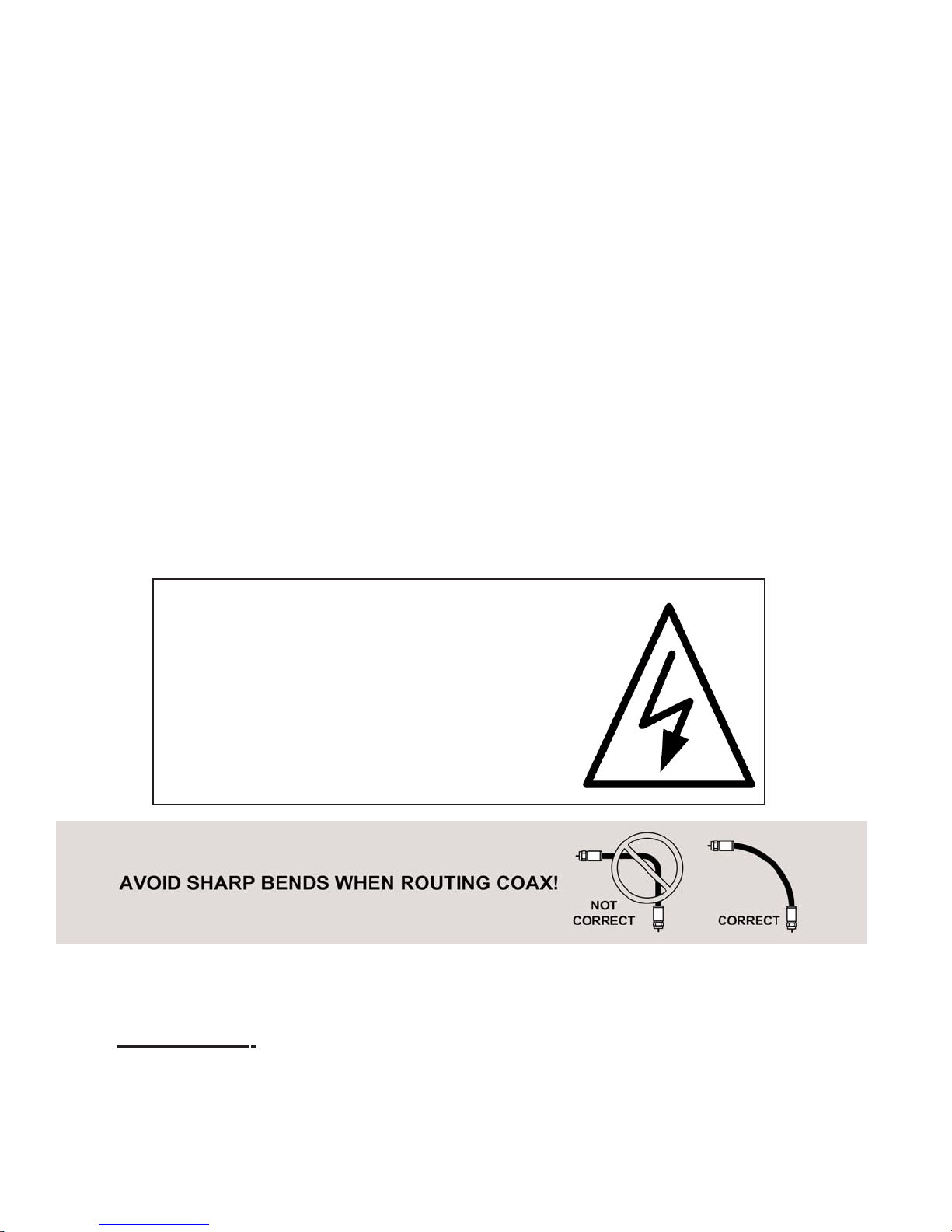
ELECTRICAL HAZARD WARNING!
The coaxial cable that connects the dome
unit to the tuner carries a 24 volt electrical
current. Exercise extreme caution when
handling this cable. Do not cut, break, or
splice this line. Do not insert or connect
any devices such as splitters or any other
device for any reason. This line is not
compatible with any other equipment.
Damage will occur to any device other than
the dome unit if connected to the antenna
port on the tuner.
DIRECTV is a registered trademark of DIRECTV, Inc.
Dish Network®is an official trademark of Echostar Communications Corporation.
Bell ExpressVu®is an official trademark of Bell Canada.
DVB®is a trademark of the DVB Digital Video Broadcast Project (1991-1996)
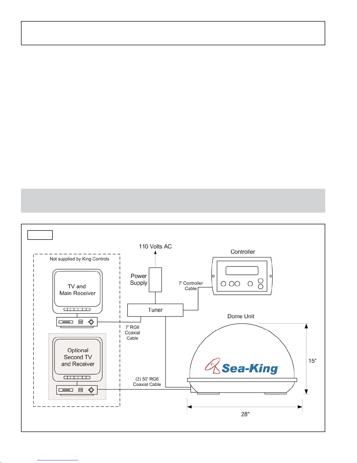
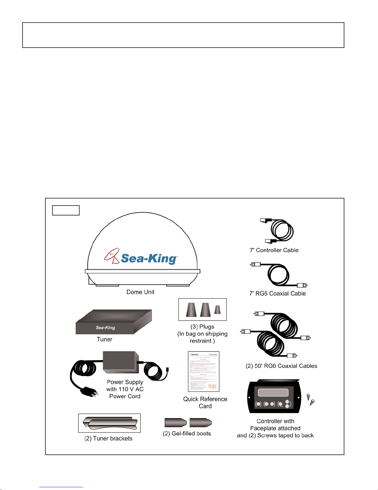
The Sea-King Fully Stabilized Marine Satellite System includes 4 main components (Fig. 1).
Dome (Antenna) Unit Mounted on the vessel. The dish is covered by a protective
dome that keeps operational components free from the
elements.
Controller Located in the vessel. Used to activate and monitor the
system, and access programming and diagnostic information.
Tuner Located in the vessel. Decodes the satellite signal so the
Sea-King locks onto and tracks the correct satellite.
Power Supply Located in the vessel. Supplies proper operating voltage to the
Sea-King.
SECTION 1 INTRODUCTION
Note: A TV, satellite receiver, and program subscription are also required for satellite TV
viewing. (Not supplied by King Controls.)
Page 2
Fig. 1
King-Dome
START/STOP DISPLAYSELECT MODIFY
Page 3
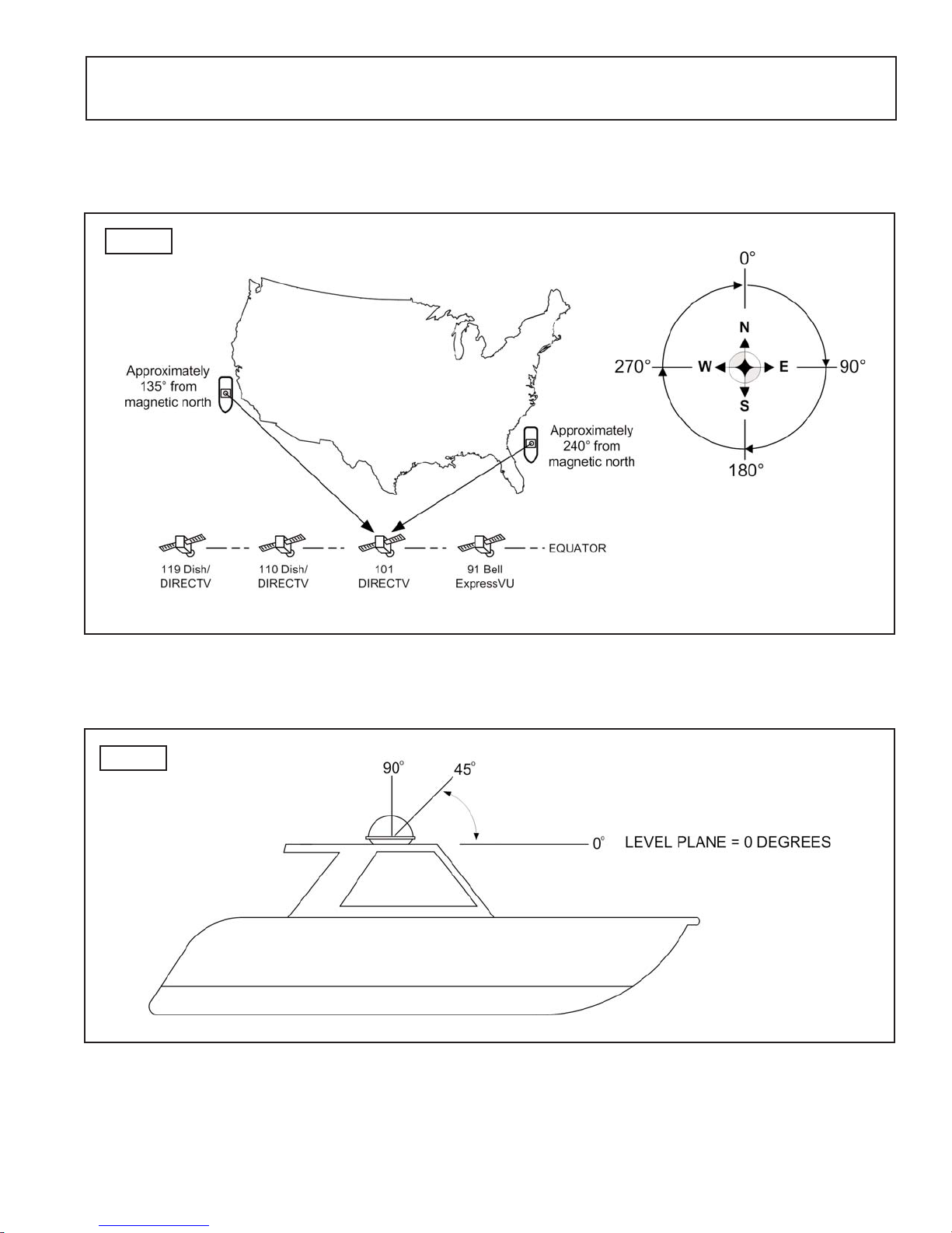
AZIMUTH: Angle in degrees measured clockwise from Magnetic North (0°) (Fig. 2).
SIGNAL STRENGTH: Intensity of electronic signal received from the satellite transmission.
SECTION 2 DEFINITION OF TERMS
Fig. 2
Fig. 3
ELEVATION: Angle in degrees measured from the ground plane (Fig. 3).
Page 4
SECTION 3 INSTALLATION
TOOLS AND MATERIALS REQUIRED:
- drill and drill bit set
- tape measure
- 7/16” open end wrench (coax connections)
- adhesive sealant (compatible with vessel material)
- appropriate fasteners to install all components and wiring
- 5/32” allen wrench, channel lock or pliers (to remove shipping bolts)
- wire cutter (to remove shipping tie strap)
KIT CONTENTS:
1. Unpack and identify all components (Fig. 4).
Fig. 4
Page 5
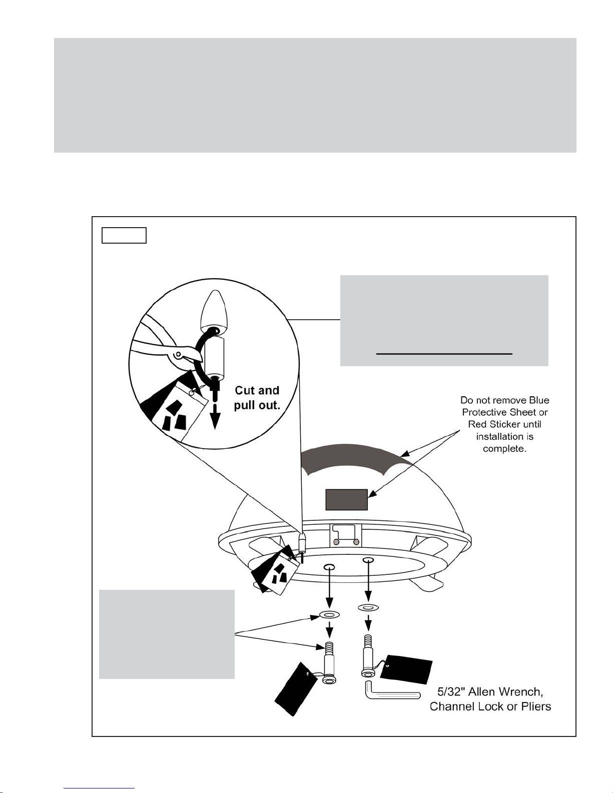
IMPORTANT! The tie strap and spacer, and the bolts and washers must be removed
from the bottom of the dome unit prior to installation. DO NOT REMOVE
THE DOME COVER TO REMOVE THESE SHIPPING RESTRAINTS.
YOU MUST PLUG THE SHIPPING RESTRAINT HOLE AND TWO SHIPPING
BOLT HOLES WITH THE SUPPLIED PLUGS. (ATTACHED TO TIE STRAP
SHIPPING RESTRAINT.)
2. Remove and discard the tie strap and spacer (KEEP RUBBER PLUGS), and the two
bolts and washers that pass through the bottom of the base (Fig. 5).
Fig. 5
IMPORTANT!
Remove and discard
Bolts and Washers
prior to installation.
IMPORTANT!
Remove and discard Tie Strap and
Plastic Spacer prior to installation.
KEEP RUBBER PLUGS.
DO NOT REMOVE DOME COVER
Page 6
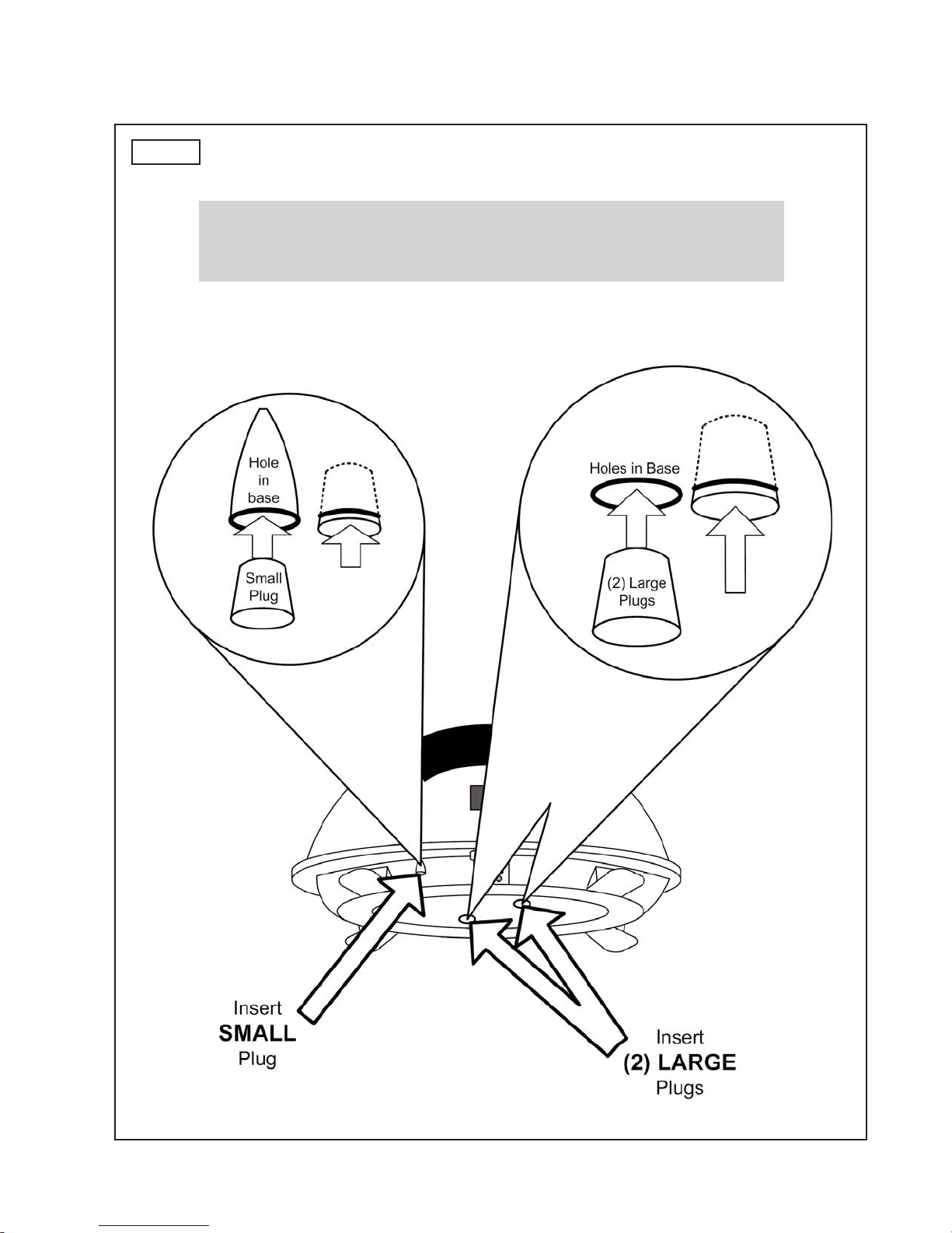
IMPORTANT!
After removing shipping restraints, firmly insert plugs into
appropriate holes. Plugs should be flush with base.
3. Insert provided plugs into holes that were occupied by tie strap and shipping bolts.
Inserted plugs should be flush with base (Fig. 6).
Fig. 6
Page 7
DOME LOCATION
1. Select an area on the vessel for the dome unit, and the location where the coax cables
will enter the vessel through the surface to the satellite receiver and internal components.
Use the following criteria:
a) The shortest distance between the dome unit and the main satellite receiver is most
desirable.
b) The dome unit requires either: 1) a 28 inch diameter FLATarea on the vessel
surface for mounting with the attached feet or 2) an industry standard mount (call
King Controls for more information).
c) The dome unit should never be mounted so that it is tilted more than two degrees
in any direction.
d) Keep the dome unit as far away from the radar as possible.
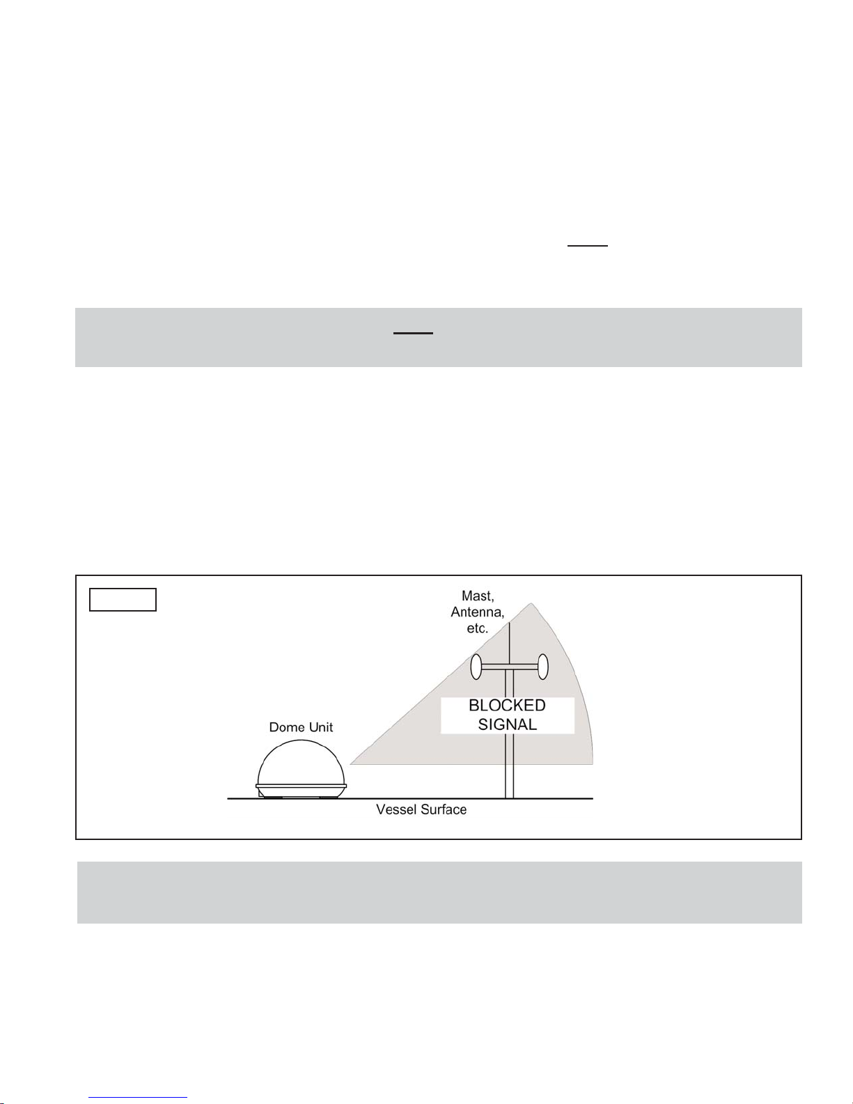
e) There must be no “line of sight” obstructions from this location. Items such as
masts or radar antennas that are too close to the dome unit may prevent the
satellite signal from reaching the dish (Fig. 7).
Fig. 7
2. Place the dome unit in the selected area.
IMPORTANT! Make sure shipping restraints are removed from bottom of dome
unit (Fig. 5, Page 5).
IMPORTANT! Mounting area must be FLAT. Base of Sea-King must not flex or deform
when attached to vessel surface or unit will not operate properly.
ELECTRICAL HAZARD WARNING!
COMPONENT LOCATION:
1. Select the location of the internal components using the following criteria:
a) The Controller, Tuner, and Power Supply should be in the same general vicinity of
the main satellite receiver, AND ACCESSIBLE FOR OPERATION AND
MAINTENANCE PURPOSES.
b) The Tuner should not be stacked directly on top of other electronics. If located in a
cabinet or other enclosure, make sure there is adequate ventilation around the unit.
(If using the Tuner mounting brackets see page 17.)
c) The Controller should be conveniently located for the end user. (If using the Wall
Mount Faceplate, see page 16.)
d) All components should be secured so they do not shift or bounce around during
vessel motion.
2. Place the components in the selected areas.
To verify proper operation of the components in their selected locations, perform a System
Location check as follows:
1. TEMPORARILY connect system as outlined in Fig. 10, Page 13.
2. Verify system operates properly as described in Section 4 OPERATION, Page 18.
3. After verifying proper operation of the system, disconnect all components.
The coaxial cable that connects the dome unit to the tuner
carries a 24 volt electrical current. Exercise extreme
caution when handling this cable. Do not cut, break, or
splice this line. Do not insert or connect any devices such
as splitters or any other device for any reason. This line is
not compatible with any other equipment. Damage will
occur to any device other than the dome unit if connected
to the antenna port on the tuner.
SYSTEM LOCATION CHECK
Page 8
Table des matières
Autres manuels Sea King Récepteur


