Scott MCX32 Manuel utilisateur

CD/MP3 CAR RADIO WITH MANUAL TUNING AND RDS FUNCTION
AM/FM STEREO
RDS FUNCTION (AF/TA/PTY)
PLAYS MP3/ID3 TAG FILES RECORDED ON CD-R/CD-RW
USB PORT & SD/MMC CARD SLOT ON FRONT PANEL
ANTI-THEFT DETACHABLE FRONT PANEL
MUSIC POWER: 28 WATT
MCX32
USER MANUAL AND INSTALLATION INSTRUCTIONS

ACCESSORIES....................................................................................................................................................................................GB-1
SAFETY.................................................................................................................................................................................................GB-2
1. INSTALLATION.................................................................................................................................................................................GB-3
2. USING THE DETACHABLE FRONT PANEL...................................................................................................................................GB-6
2.1 Removing the front panel.............................................................................................................................................................GB-6
2.2 Installing the front panel...............................................................................................................................................................GB-6
3. Wiring Diagram................................................................................................................................................................................GB-7
4. OPERATION.....................................................................................................................................................................................GB-8
4.1 Features and Controls..................................................................................................................................................................GB-8
4.2 General Operation........................................................................................................................................................................GB-9
4.3. Radio Operation........................................................................................................................................................................GB-11
4.4. RDS (Radio Data System) Operation.......................................................................................................................................GB-12
4.5. CD/MP3 Operation....................................................................................................................................................................GB-12
4.6 USB device and SD/MMC card Operations...............................................................................................................................GB-15
4.7 AUX IN Operation.......................................................................................................................................................................GB-15
5. DISC NOTES..................................................................................................................................................................................GB-16
5.1 Notes on discs............................................................................................................................................................................GB-16
5.2 Notes on CD-Rs/CD-RWs..........................................................................................................................................................GB-16
5.3. Handling and Cleaning..............................................................................................................................................................GB-16
5.4 Precautions when using new discs............................................................................................................................................GB-17
6. TECHNICAL SPECIFICATIONS.....................................................................................................................................................GB-18
7. TROUBLESHOOTING....................................................................................................................................................................GB-19
7. TROUBLESHOOTING GB-19
Contents
GB-1
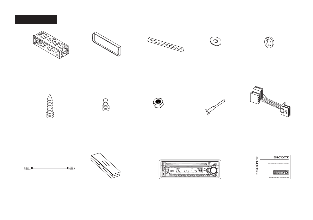
ACCESSORIES
Mounting Bracket
(Half Sleeve)
X1
Outer trim ring
X1
Small Metal Strip
X1
Plain Washer
X1
Release key
X2
Protective case
X1
Hex Nut
X1
ISO Wire connector
X1
Removable control panel
X1
User manual
X1
Spring Washer
X2
Tapping Screw
X1
Screw
X4
AM/FM STEREO
RDS FUNCTION (AF/TA/PTY)
PLAYSMP3/ID3 TAG FILES RECORDED ON CD-R/CD-RW
FRONT PANELUSB PORT & SD/MMC CARD SLOT
ANTI-THEFT DETACHABLEON FRONT PANEL
MUSIC POWER: 28 WATT
MCX32
USB Adaptor Cable
X 1

GB-2
This unit is designed and manufactured with the users safety in mind, however any improper use or operation may result in certain
dangers. It is therefore highly recommended to read this manual thoroughly and adhere to the following precautions.
Safety precautions
To prevent an electrical shock, do not open the housing of the unit. In any case of malfunctioning, only have the unit serviced by an
approved and qualified service centre.
Do not expose to any water or to a very humid environment. Do not operate the unit when your hands are wet as this may cause a
short circuit.
For safe driving, keep the volume low in order to concentrate on traffic conditions.
Do not clean the unit with alcohol, only clean with a soft dry cloth.
If the unit has been kept at a high temperature or in a high humidity environment, cool down the car interior before turing on the unit.
Do not use the unit for a long time without running the vehicle engine, it may drain the battery and the vehicle engine may not be
able to start.
Before final installation in the dashboard opening, connect the wiring and make sure the unit is working property.
Only use parts provided with the unit to ensure proper installation.
Do not route wiring in places that the heat may melt the wiring insulation.
When replacing the fuse, ensure that the new fuse has the capacity recommended by the manufacturer.
Operation precautions
Do not operate the player with scratched, bent or broken discs. When a disc is not loaded properly, do not force it into the disc
loader.
Never insert any other objects into the disc loader like a coin or pin, etc as this may cause damage or a short circuit.
Do not use different disc formats other than 12cm round discs.
If the unit is disconnected to the battery, it will lose memorized data.
If the source disc has poor sound quality due to scratches, dirt or a bad recording, the playback sound quality may be poor.
*
*
*
*
*
*
*
*
*
*
*
*
*
*
*
SAFETY

GB-3
Notes:
- Before the installation of the unit, make the electrical connections and ensure everything is connected properly and that the unit works
correctly.
- Consult your dealer if installation requires the drilling of holes or other modifications of the vehicle.
- Install the unit where it does not get in the driver’s way and cannot injure the passenger if there is a sudden stop, like an emergency
stop.
- If installation angle exceeds 30° from horizontal, the unit may not perform properly.
Remove the CD mechanism transit screws before installation
Before installing the unit, remove the two screws which are labelled “REMOVE SCREW”.
Installation opening on the dashboard
This unit can be installed in any dashboard opening with the following dimensions (DIN standard):
Installing the unit
After making all the connections, ensure that the unit is working properly, then follow these steps to install the unit.
1. Make sure the ignition is turned off. Disconnect the cable from the vehicle battery negative (-) terminal.
2. Disconnect the wire harness and the antenna.
3. Press the REL ( ) button to remove the control panel (for details, refer to ‘USING THE DETACHABLE FRONT PANEL’).
1. INSTALLATION

GB-4
4. If necessary, remove the outer trim ring.
5. The two supplied keys release tabs inside the unit’s sleeve so you can remove it. Insert the left (“L”) and right (“R”) release key as
far as they will go (with the notches facing up) into the appropriate slots at the center of the left and right sides of the unit. Then slide
the sleeve off the back of the unit.
6. Fit the sleeve by inserting it into the opening of the dashboard and bend back the tabs located around the sleeve with a screwdriver.
Not all tabs will be able to make contact, so you will need to select the tabs which will be most effective with your dashboard.
7. Reconnect the wire harness and the antenna, being careful not to pinch any wires or cables.
8. If necessary, use the metal strap and hardware (M5mm hex nut and spring washer) to attach one end of the strap to the mounting
bolt on the back of the unit. If necessary, bend the metal strap to fit it into the dashboard. This metal strap also helps to ensure proper
electrical grounding of the unit.
9. Slide the unit into the sleeve until it fits correctly.

GB-5
10. Reconnect the cable to the vehicle battery’s negative (-) terminal. Then replace the outer trim ring and install the unit’s front panel
(see the steps of ‘Installing the front panel’).
Removing the unit
1. Make sure the ignition is turned off, and then disconnect the cable from the negative (-) terminal of the vehicle’s battery.
2. Press the REL ( ) button to remove the front panel.
3. Remove the top of the outer trim ring by pulling it out.
4. Insert both of the supplied keys into the slots at the middle of the left and right sides of the unit then pull the unit out of the
dashboard.
5. Disconnect the wire harness and the antenna, and disassemble the metal bar attached to the back of the unit (if present).

GB-6
2.2 Installing the front panel
First, fit the left side of the front panel and then fit the right side of the front panel until you hear a click sound. If the panel is not properly
fixed in the unit, some of the keys or the display may not function properly. If this occurs, remove and re-install the front panel.
Precautions when handling
1. Do not drop the front panel.
2. Do not put pressure on the display or control buttons when removing or installing the front panel.
3. Do not touch the back of the front panel or the main unit once the panel has been removed as you may dirty the contacts or damage
them.
4. If any dirt or foreign substances are present on the contacts, they can be removed with a clean and dry cloth.
5. Do not expose the front panel to high temperatures or direct sunlight.
6. Do not allow the unit to come into contact with any liquids (in particular volatile liquids such as benzene, paint thinner or insecticides).
2.1 Removing the front panel
Press the REL ()button
on the front panel.
Pull off the front panel. Place the front panel into the
protective case provided.
Fig.1 Fig.2 Fig.3
2. USING THE DETACHABLE FRONT PANEL

GB-7
ISO CONNECTOR
Part A
A1: /
A2: /
A3: /
A4: Battery B+ (10A FUSE) (Yellow)
A5: Electric antenna (Blue)
A6: /
A7: + after ignition (Red)
A8: Ground B- (Black)
Part B
B1: Rear Right + (Violet)
B2: Rear Right - (Violet/Black)
B3: Front Right + (Grey)
B4: Front Right - (Grey/Black)
B5: Front Left + (White)
B6: Front Left - (White/Black)
B7: Rear Left + (Green)
B8: Rear Left - (Green/Black)
3. Wiring Diagram
RCA cables not supplied (only concerns the use of an external amplifier – not included)

GB-8
4.1 Features and Controls
1) Front panel
2) Main unit of the car radio
1 SD/MMC CARD SLOT
2(Next Track) button
3 DISC SLOT
4 LCD display
5 SEL (select) button
6EJECT ( ) button
7 VOL +/- button
8REL (RELEASE) button
9 USB PORT
10 (Previous Track) button
11 AUX Input Jack
12 MOD/ENTER button
13 BND/LOU (loudness)/MP3 button
14 DISP (display) button
15 SCN (Scan), EQ (equalizer) button
16 SHF (shuffle) button
17 MON (Stereo/Mono select),
TA (Traffic Announcement) button
18 RPT (Repeat Mode select),
AF (Alternative Frequency) button
19 PLAY/PAUSE ( )/MUTE button
20 TUNING Knob
21 POWER ( ) button
22 REMOVEABLE CONTROL PANEL
23 LED ANTI-THEFT INDICATOR
24 RESET button
4. OPERATION
Table des matières
Autres manuels Scott Récepteur de voiture

Scott
Scott DRX 2002 Manuel utilisateur

Scott
Scott DRX600 Manuel utilisateur

Scott
Scott XRB300 RC - S Manuel utilisateur

Scott
Scott A2 Manuel utilisateur

Scott
Scott XPC1G - S Manuel utilisateur

Scott
Scott SRX280 - S Manuel utilisateur

Scott
Scott IXCR 100 - S Manuel utilisateur

Scott
Scott DRX950 - S Manuel utilisateur

Scott
Scott SRX190 Manuel utilisateur


