schroff VXS64 Series Manuel utilisateur
VXS/VME64x Tower System
User’s Manual
Product No.:
10836-060
May 04, 2009Doc-No: 63972-161_R1.1
Impressum:
Schroff GmbH
D-75334 Straubenhardt, Germany
The details in this manual have been carefully compiled and
checked - supported by certified Quality Management System
to EN ISO 9001/2000
The company cannot accept any liability for errors or misprints.
The company reserves the right to amendments of technical
specifications due to further development and improvement of
products.
Copyright © 2007
All rights and technical modifications reserved.
Rev. Date updated Change
R1.0 November 12, 2007 Initial Release
R1.1 May 04, 2009 Technical data fans updated

VXS/VME64x Tower System
10836-060
www.schroff.biz I R1.1, May 04, 2009
Table of Contents
1 Safety................................................................................................................. 1
1.1 Intended Application............................................................................................ 1
1.2 Safety Instructions............................................................................................... 2
1.3 Safety Symbols used in this document................................................................ 2
1.4 General Safety Precautions................................................................................. 2
1.5 References and Architecture Specifications........................................................ 3
2 Product Definition............................................................................................. 4
2.1 Mechanical Overview........................................................................................... 5
2.2 Tower System...................................................................................................... 6
2.3 VXS/VME64x Backplane..................................................................................... 6
2.4 Power Supply....................................................................................................... 7
2.4.1 Grounding.............................................................................................. 8
2.4.2 Power Supply......................................................................................... 8
2.4.3 Wiring Diagram...................................................................................... 9
2.5 Thermals............................................................................................................ 10
2.6 Fan Control Module (FCM)................................................................................ 11
2.7 Display Module.................................................................................................. 11
3 Installation....................................................................................................... 12
3.1 Unpacking.......................................................................................................... 12
3.1.1 Ensuring Proper Airflow....................................................................... 12
3.2 Basic Functional Check..................................................................................... 13
4 Service............................................................................................................. 14
4.1 Technical support and Return for Service Assistance....................................... 14
4.2 Declaration of Conformity.................................................................................. 14
4.3 Scope of delivery............................................................................................... 15
4.4 Accessories ....................................................................................................... 15
4.5 Spare Parts........................................................................................................ 15
5 Technical Data ................................................................................................ 16
6 Dimensions ..................................................................................................... 17

VXS/VME64x Tower System
10836-060
www.schroff.biz II R1.1, May 04, 2009

VXS/VME64x Tower System Safety
10836-060
www.schroff.biz 1 R1.1, May 04, 2009
1 Safety
1.1 Intended Application
The VXS/VME64x Tower System, described in this manual, is intended as a
platform for a microcomputer system based on the VXS/VME bus system (VME
(VITA 1-1994), VME64x (VITA 1.1-1997), VXS (VITA 41.0/1/10/11)).
The VXS/VME64x Tower System is designed for protection class IP 20 and can
be used only in the resp. environments.
VXS/VME64x Tower Systems are not end-products, so there is no valid
approval for this unit. In order to enable stand-alone functionality, additional
elements are required. An operational system is achieved only by way of
appropriate VXS or VME64x boards.
The completion and final testing of the units have been carried out, or at least
supervised, by qualified technicians. These instructions are directed exclusively
to these qualified technicians i.e.engineers, trained and qualified electricians
etc.
Make sure that:
• the assembled unit complies with the safety regulations currently applicable
in the country it is going to be used.
• the overall unit complies with all other regulations and specifications at the
place and country of use, e.g. interference limits, approval by the telecom-
munications authorities.
VXS/VME64x Tower System Safety
10836-060
www.schroff.biz 2 R1.1, May 04, 2009
1.2 Safety Instructions
The intended audience of this User’s Manual is system integrators and
hardware/software engineers.
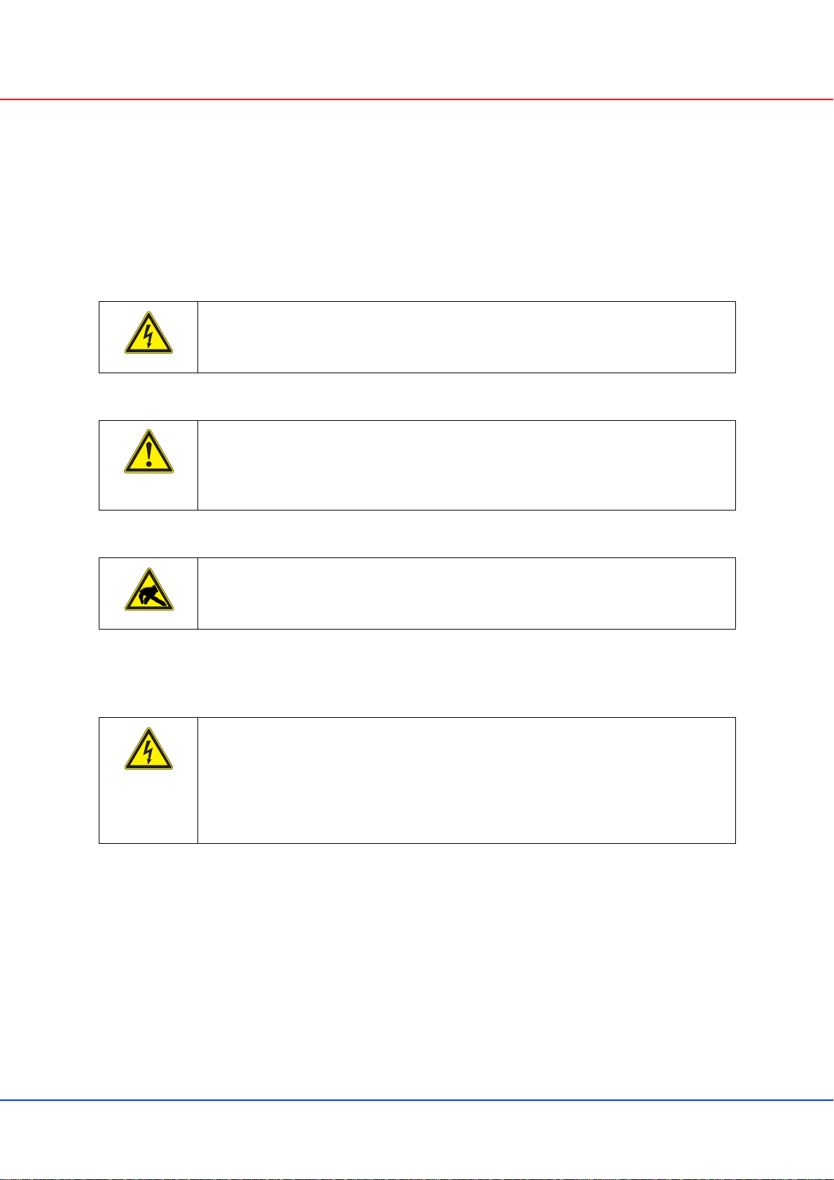
1.3 Safety Symbols used in this document
1.4 General Safety Precautions
• Service personnel must know the necessary electrical safety, wiring and
connection practices for installing this equipment.
• Install this equipment only in compliance with local and national electrical
codes.
Hazardous voltage!
This is the electrical hazard symbol. It indicates that there are dangerous
voltages inside the Shelf.
Caution!
This is the user caution symbol. It indicates a condition where damage of the
equipment or injury of the service personnel could occur. To reduce the risk of
damage or injury, follow all steps or procedures as instructed.
Danger of electrostatic discharge!
TheShelfcontainsstaticsensitivedevices.Topreventstaticdamageyoumust
wear an ESD wrist strap.
Warning!
Voltages over 60 VDC can be present in this equipment. This equipment is
intended to be accessed, to be installed and maintained by qualified and
trained service personnel only.
This equipment is designed in accordance with protection class 1!
It must therefore be operated only with protective GND/earth connection!
VXS/VME64x Tower System Safety
10836-060
www.schroff.biz 3 R1.1, May 04, 2009
1.5 References and Architecture Specifications
• User Manual VME64x Backplanes
Order no.: 73972-103
• Short Form User Manual VXS/VME64x Backplane 23001-701
Order no.: 73972-125
• User Manual Fan Control Module (FCM)
Order no.: 73972-083
• User Manual Power Supply
Order no.: 73972-077
• User Manual Power Backplane
Order no.: 73972-072
For more information see the catalogue „Electronic Packaging“ and at
www.schroff.biz

VXS/VME64x Tower System Product Definition
10836-060
www.schroff.biz 4 R1.1, May 04, 2009
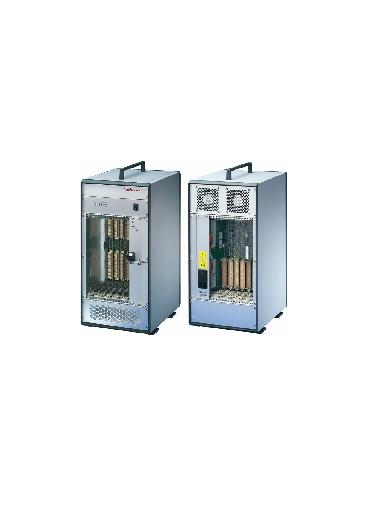
2 Product Definition
The Schroff VXS/VME64x Tower System consists of:
• A shielded subrack with front assembly area for 7 front boards
(6 U, 160 mm deep) and rear assembly area for 7 Rear I/O boards
(6 U, 80 mm deep)
• A Backplane with 4 slots VME64x (VITA 1.1-1997), 3 VXS slots
(VITA 41.0/1/10/11) and 2 P47 connectors for plug-in power supplies
• A 19“ plug-in power supply with wide range input
• Speed controlled fans for cooling the boards
• Fan Control Module (FCM) for fan monitoring/controlling
• Display module
• Mains/line switch
• AC mains/line module with IEC320-C14 connector, line filter and fuses
The fans are assembled at the rear panel, one power supply is plugged-in right
to the card cage.
VXS/VME64x Tower System Product Definition
10836-060
www.schroff.biz 5 R1.1, May 04, 2009
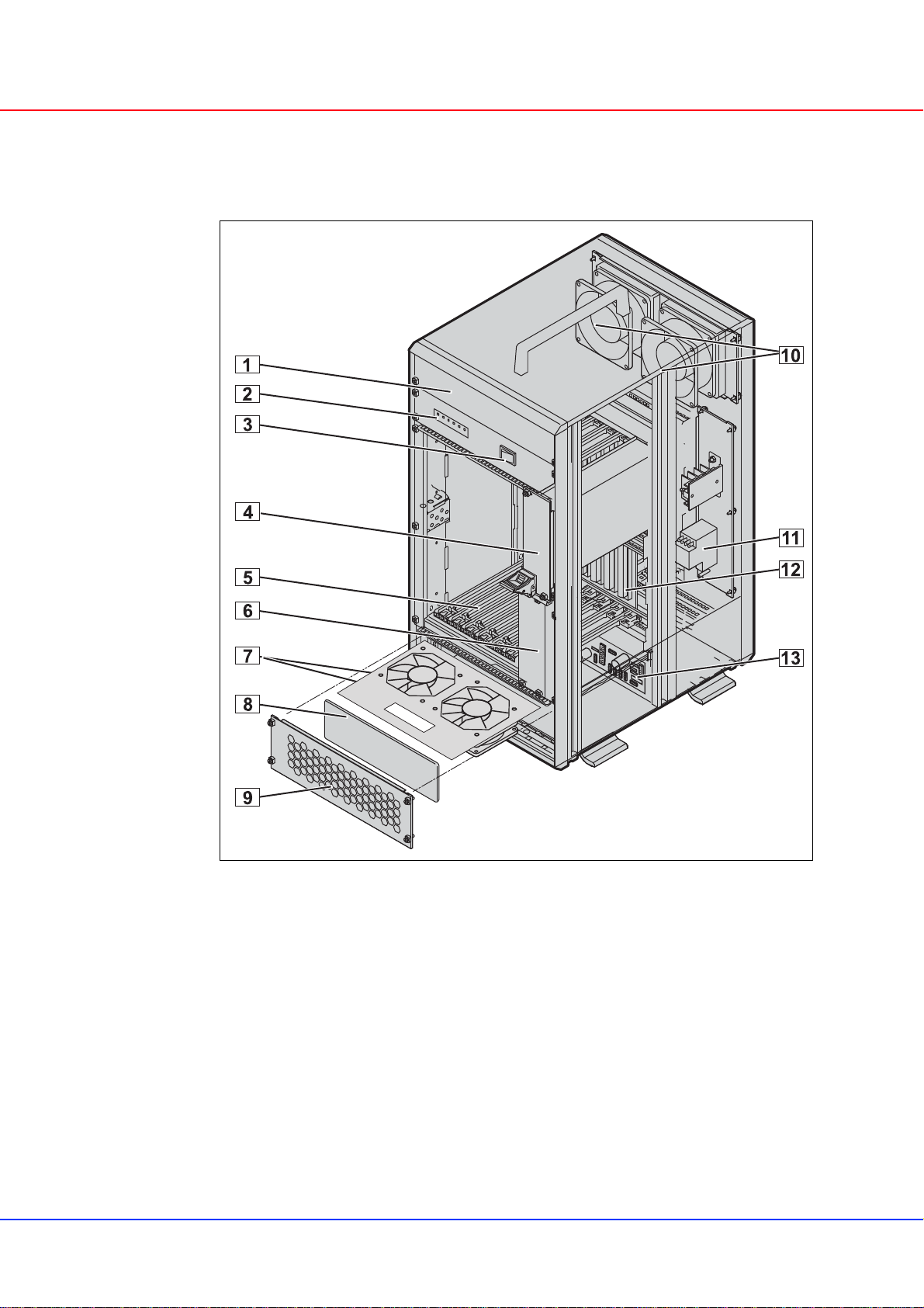
2.1 Mechanical Overview
Figure 1: Mechanical Overview
10007848
1 Front panel 5 U / 8 HP 8 Air Filter
2 Display Module 9 Front panel, perforated
3 AC Switch 10 Rear Fans
4 19“ Power Supply 11 AC Connector (IEC320-C14) with
filter and fuses
5 Card Cage with Guide Rails 12 VXS/VME64x Backplane
6 Front panel 3 HE / 8 TE 13 Fan Control Module (FCM)
7 Front fans
VXS/VME64x Tower System Product Definition
10836-060
www.schroff.biz 6 R1.1, May 04, 2009
2.2 Tower System
The VXS/VME64x Tower System system based on the Schroff europacPro
subrack in a ratiopacPro chassis with EMC shielding. The front card cage
providesspaceforthe installationof 7VXS/VME64x Boards(6 U, 4HP, 160mm
deep),the rear card cage providesspace for the installation of 7 Rear I/O Boards
(6 U, 4 HP, 80 mm deep).
The lower guide rails are fitted with ESD clips.
Two slots for 19“ plug-in power supplies are located right to the card cage.
2.3 VXS/VME64x Backplane
The6U Backplaneprovides4 VME64xslotswith P0connectors, 3VXSpayload
slots and 2 power supply slots with P47 connectors. There is no switch slot. The
high-speed links are routed in a bidirectional ring topology (Full Mesh).
For more information about this VXS/VME64x Backplane (#23001-701), please
see in the catalogue and at www.schroff.biz.
1 Slot = 4 HP = 20,32 mm
Ce manuel convient aux modèles suivants
2
Table des matières


