
Schneider Airsystems FP-M Instructions d'installation

G880580_001
2010/11/risa-14/11
Originalbedienungsanleitung Teil 1 I/1 Teil 2 II/1
Original operating manual Part 1 I/2 Part 2 II/4
Notice d’utilisation d’origine Partie 1 I/3 Partie 2 II/7
Manual de instrucciones original Parte 1 I/4 Parte 2 II/11
Originele gebruiksaanwijzing Deel 1 I/5 Deel 2 II/15
Originalbruksanvisning Del 1 I/6 Del 2 II/18
Oryginalna instrukcja eksploatacji
Części 1
I/7
Części 2
II/21
Eredeti kezelési utasítás
1. rész
I/8
2. rész
II/25
Originál návodu k obsluze
Část
1I/9
Část
2 II/28
Originálny návod na obsluhu
Čas
ť1I/10
Čas
ť2 II/31
Оригинал Руководство по эксплуатации
Часть 1
I/11
Часть 2
II/34
FP - M
D 040 025
FP - A
D 040 026

0,41
pmax
10
A
P
2-10
LWA
HT
B
m
10 m
6
396 190x61,5x
1,5
04
06
03
02
01
05
08 07
80
p
out
i
m
L
Q
400
1:40
0,6 400
220
Q
60
L
0,2
FP-M
D040025
Q
140
FP-A
D040026
L
0,78
FP-A
D040026
FP-M
D040025 +
03

2a
05
1a
1b
05
2b
10
05
09


FP-M / FP-A
I/1
D
Inhaltsverzeichnis - Teil 1
1.1 Lieferumfang
– Fettpresse
– Fettschlauch
– Bedienungsanleitung
1.2 Bestimmungsgemäße Ver-
wendung
Das druckluftbetriebene Gerät für den hand-
werklichen Einsatz eignet sich zum:
Schmieren von Teilen an Fahrzeugen, Ma-
schinen, Transport- und Beförderungsanla-
gen.
Jede andere Verwendung ist zweckentfrem-
det.
1.3 Technische Daten
siehe Bild A
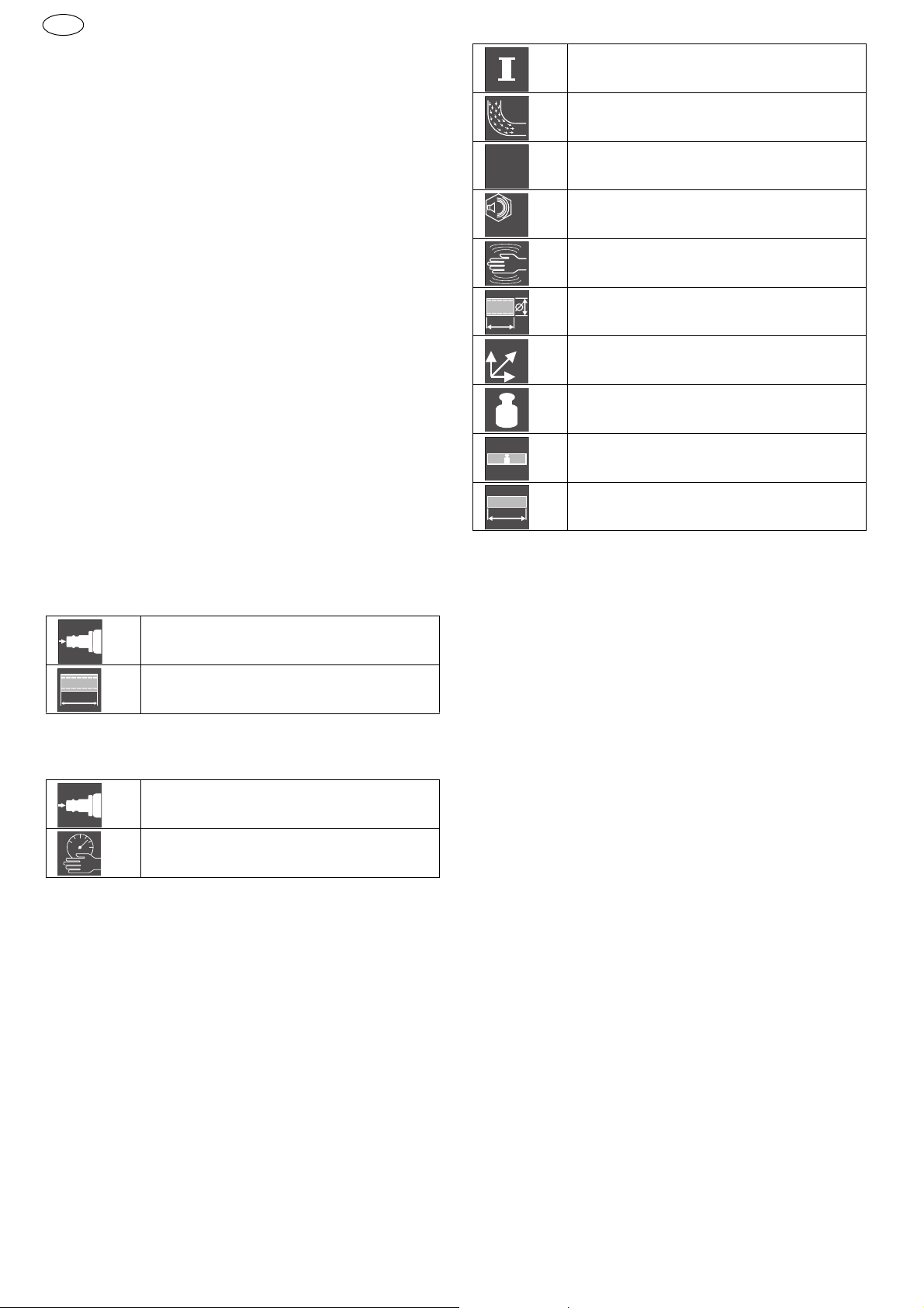
1.4 Symbole und ihre Bedeutung
Produktspezifische technische Daten
Allgemeine technische Daten
(FP-M / FP-A)
1.5 Aufbau
1.1 Lieferumfang............................ 1
1.2 Bestimmungsgemäße Verwen-
dung ....................................... 1
1.3 Technische Daten...................... 1
1.4 Symbole und ihre Bedeutung...... 1
1.5 Aufbau .................................... 1
Maximaler Luftverbrauch [l/min]
Schlauchlänge [m]
Q
L
Maximal zulässiger Druck [bar]
Arbeitsdruck [bar]
Luftbedarf bei 6 bar [l/Hub]
Maximaler Ausgangsdruck [bar]
Druckübersetzung
Schallleistungspegel L
WA
nach
DIN 45635-20 [dB(A)]
Vibration nach ISO 8662 [m/s
2
]
Empfohlener Schlauchdurchmes-
ser (innen) bei L= 10 m [mm]
Abmessungen: Höhe x Tiefe x
Breite [mm]
Gewicht [kg]
Maximales Gewicht (Kartusche)
[g]
Maximale Länge (Kartusche)
[mm]
01 Stecknippel
02 Abzugshebel
03 Entlüftungsventil
04 Fettschlauch
05 Fettbehälter
06 Füllnippel
07 Griffstück
08 Sicherungshebel
09 Fettkolben
10 Dichtung
pmax
P
Q
p
out
i
LWA
10 m
HT
B
m
m
L

I/2
FP-M / FP-A
GB
Table of contents - Part 1
1.1 Scope of delivery
–Greasegun
–Greasehose
– Instruction manual
1.2 Conventional use
The compressed air tool is an industrial tool
suitable for:
Lubricating components on vehicles, ma-
chines, transport and conveyor systems.
Any other type of use is considered contrary
to the intended use.
1.3 Technical data
see Figure A
1.4 Symbols and their meaning
Product-specific technical data
General technical data
(FP-M / FP-A)
1.5 Components
1.1 Scope of delivery ...................... 2
1.2 Conventional use ...................... 2
1.3 Technical data .......................... 2
1.4 Symbols and their meaning ........ 2
1.5 Components............................. 2
Maximum air consumption [l/
min]
Hose length [m]
Max. permissible pressure [bar]
Working pressure [bar]
Q
L
pmax
P
Air requirements at 6 bar [l/
stroke]
Maximum output pressure [bar]
Pressure ratio
Sound power level L
WA
according
DIN 45635-20 [dB(A)]
Vibrations as per ISO 8662
[m/s
2
]
Recommended hose diameter
(inner) at L= 10 m [mm]
Overall dimensions: width x
depth x height [mm]
Weight [kg]
Maximum weight (cartridge) [g]
Maximum length (cartridge)
[mm]
01 Plug nipple
02 Trigger lever
03 Venting valve
04 Grease hose
05 Grease reservoir
06 Filling nipple
07 Handle piece
08 Safety lever
09 Grease plunger
10 Gasket
Q
p
out
i
LWA
10 m
HT
B
m
m
L

FP-M / FP-A
I/3
F
Table des matières - partie 1
1.1 Eléments fournis
– Seringue à graisse
– Flexible à graisse
– Mode d'emploi
1.2 Consignes d'utilisation
Cet appareil pneumatique à destination des
artisans a été conçu pour :
la lubrification des pièces d'automobiles, de
machines, de systèmes de transport et de
convoyage.
Toute autre utilisation est détournée de sa
destination première.
1.3 Caractéristiques techniques
cf. fig. A
1.4 Les pictogrammes et leur si-
gnification
Caractéristiques techniques spécifiques
aux modèles
Caractéristiques techniques générales
(FP-M / FP-A)
1.5 Structure
1.1 Eléments fournis....................... 3
1.2 Consignes d'utilisation ............... 3
1.3 Caractéristiques techniques........ 3
1.4 Les pictogrammes et leur signifi-
cation...................................... 3
1.5 Structure ................................. 3
Consommation d'air maximale
[l/min]
Longueur de flexible [m]
Pression maximale admissible
[bar]
Q
L
pmax
Pression de service [bars]
Besoins en air à 6 bars [l/
course]
Pression de sortie maximale
[bar]
Rapport de pression
Niveau de puissance acoustique
L
WA
selon DIN 45635-20 [dB(A)]
Vibrations selon ISO 8662
[m/s
2
]
Diamètre (intérieur) de tuyau
souple recommandé pour
L = 10 m [mm]
Dimensions : hauteur x profon-
deur x largeur [mm]
Poids [kg]
Poids maximal (cartouche) [g]
Longueur maximale (cartou-
che) [mm]
01 Raccord à enficher
02 Gâchette
03 Soupape d'évacuation d'air
04 Flexible à graisse
05 Réservoir de graisse
06 Nipple de remplissage
07 Poignée
08 Levier de déclenchement
09 Piston à graisse
10 Joint
P
Q
p
out
i
LWA
10 m
HT
B
m
m
L

I/4
FP-M / FP-A
E
Índice - Parte 1
1.1 Suministro
– Pistola engrasadora
– Manguera para grasa
– Manual de instrucciones
1.2 Uso previsto
Este aparato accionado por aire comprimido
de uso profesional es adecuado para:
Lubricar piezas de vehículos, máquinas e ins-
talaciones de transporte.
Cualquier otro uso se considera inadecuado.
1.3 Datos técnicos
véase la fig. A
1.4 Los símbolos y su significado
Datos técnicos específicos del producto
Datos técnicos generales
(FP-M / FP-A)
1.5 Composición
1.1 Suministro ............................... 4
1.2 Uso previsto............................. 4
1.3 Datos técnicos.......................... 4
1.4 Los símbolos y su significado ...... 4
1.5 Composición............................. 4
Consumo máximo de aire [l/
min]
Longitud de manguera [m]
Máx. presión admisible [bar]
Presión de trabajo [bar]
Consumo de aire a 6 bar [l/
carrera]
Q
L
pmax
P
Q
Presión de salida máxima [bar]
Relación de presión
Nivel de potencia sonora L
WA
según DIN 45635-20 [dB(A)]
Vibración según ISO 8662
[m/s
2
]
Diámetro (interior) de manguera
recomendado para L= 10 m
[mm]
Dimensiones: alto x profundi-
dad x ancho [mm]
Peso [kg]
Peso máximo (cartucho) [g]
Longitud máxima (cartucho)
[mm]
01 Boquilla insertable
02 Gatillo
03 Válvula de despresurización
04 Manguera para grasa
05 Depósito de grasa
06 Boquilla de llenado
07 Empuñadura
08 Palanca de seguridad
09 Pistón de engrase
10 Junta
p
out
i
LWA
10 m
HT
B
m
m
L

FP-M / FP-A
I/5
NL
Inhoudsopgave - deel 1
1.1 Leveringsomvang
–Vetpers
–Vetslang
– Gebruiksaanwijzing
1.2 Toepassing conform de bepa-
lingen
Het met perslucht aangedreven apparaat
voor handwerk is geschikt voor:
Smeren van noderdelen van voertuigen, ma-
chines, transport- en transportinstallaties.
Ieder ander gebruik is oneigelijk.
1.3 Technische gegevens
zie afbeelding A
1.4 Symbolen en hun betekenis
Productspecifieke technische gewge-
vens
Algemene technische gegevens
(FP-M /
FP-A)
1.5 Opbouw
1.1 Leveringsomvang...................... 5
1.2 Toepassing conform de bepalin-
gen......................................... 5
1.3 Technische gegevens................. 5
1.4 Symbolen en hun betekenis........ 5
1.5 Opbouw................................... 5
Maximaal luchtverbruik [l/min]
Slanglengte [m]
Max. toelaatbare druk [bar]
Werkdruk [bar]
Q
L
pmax
P
Luchtverbruik bij 6 bar [l/slag]
Uitgangsdruk maximaal [bar]
Drukoverdracht
Geluidsvermogensniveau L
WA
conform DIN 45635-20 [dB(A)]
Trilling conform ISO 8662
[m/s
2
]
Aanbevolen slangdoorsnede
(binnen) bij L= 10 m [mm]
Afmetingen: hoogte x diepte x
breedte [mm]
Gewicht [kg]
Gewicht maximaal (Cartridge)
[g]
Lengte maximaal (Cartridge)
[mm]
01 Steeknippel
02 Aftaphendel
03 Ontluchtingsklep
04 Vetslang
05 Vetreservoir
06 Vulnippel
07 Greepstuk
08 Veiligheidshefboom
09 Vetzuiger
10 Afdichting
Q
p
out
i
LWA
10 m
HT
B
m
m
L
I/6
FP-M / FP-A
N
Innholdsfortegnelse – del 1
1.1 Innholdet i esken
–Fettpresse
–Fettslange
–Bruksanvisning
1.2 Hensiktsmessig bruk
Det trykkluftdrevne utstyret egner seg til:
Smøring av deler på kjøretøy, maskiner og
transportanlegg.
All annen bruk er uhensiktsmessig bruk.
1.3 Tekniske data
Se bilde A
1.4 Symboloversikt
Produktspesifikke tekniske opplysnin-
ger
Generelle tekniske opplysninger
(FP-M /
FP-A)
1.5 Oppbygning
1.1 Innholdet i esken ...................... 6
1.2 Hensiktsmessig bruk ................. 6
1.3 Tekniske data ........................... 6
1.4 Symboloversikt......................... 6
1.5 Oppbygning ............................. 6
Maksimalt luftforbruk [l/min]
Slangelengde [m]
Maksimalt tillatt trykk [bar]
Arbeidstrykk [bar]
Q
L
pmax
P
Luftbehov ved 6 bar [l/Hub]
Maksimalt utgangsstykk [bar]
Trykkutveksling
Lydtrykksnivå i henhold L
WA
til
DIN 45635-20 [dB(A)]
Vibrasjon i samsvar med ISO
8662 [m/s
2
]
Anbefalt slangediameter (inn-
vendig) ved L = 10 m [mm]
Mål: høyde x dybde x bredde
[mm]
Vekt [kg]
Maksimal vekt (patron) [g]
Maksimal lengde (patron) [mm]
01 Stikknippel
02 Avtrekker
03 Lufteventil
04 Fettslange
05 Fettbeholder
06 Påfyllingsnippel
07 Gripestykke
08 Sikringsarm
09 Fettstempel
10 Tetning
Q
p
out
i
LWA
10 m
HT
B
m
m
L
Ce manuel convient aux modèles suivants
3
Table des matières
Langues :


