SANTA LUCIA D556 Mode d’emploi
INSTRUCTION MANUAL WARRANTY CERTIFICATE
SANTA LUCIA
BY
TM
U.S. Patents: D556,882; D559,436; D568,984; D570,986;
D574,948; D599,000; D599,466; 5,554,006
© 2006 Minka Lighting, Inc.
by

This product is protected by United States Federal and/or State Law, including Patent, Trademark and/or Copyright laws.
Manual design and all elements of manual design are protected by U.S. Federal and/or State Law, including Patent, Trademark and/or Copyright laws.
Minka-Aire warrants to the original owner that this fan will be free from defects in material and workmanship for one
year from the date of purchase, excluding the motor. Minka-Aire warrants to the original owner that the motor in this fan
shall be free from defects in material and workmanship for as long as the original purchaser owns the fan, and it remains in
the original installation.
This is a limited warranty. Minka-Aire's only obligation under this limited warranty is to replace or repair, or refund the purchase price, in
Minka-Aire's sole discretion without charge to the original owner, of the fan once Minka-Aire confirms that the fan has a defect covered by this
limited warranty.
Call our customer service department at 1-800-307-3267 to obtain the name of the Minka-Aire authorized dealer closest to your location, or
contact us through our web site, www.minkagroup.net and write to: Ask Mr. Minka if you have any questions or require further assistance.
To obtain warranty service, the owner should return the fan along with proof of purchase to a Minka-Aire authorized dealer. The Minka-Aire
authorized dealer shall then, at its sole discretion: repair the fan, replace the fan, refund the purchase price less the amount directly attributable to
the consumer's prior usage of the fan, or if necessary instruct the consumer to contact Minka-Aire directly for warranty service. Minka-Aire will be
responsible for the cost of any repair, or replacement for any warranty service provided by a Minka-Aire authorized dealer for product under
warranty.
You may also at your preference obtain warranty service by returning the fan directly to Minka-Aire along with proof of purchase, your name
and return address, and a description of the claimed product defect. Pack carefully; damage sustained in return transit to Minka-Aire will be the
original owner's responsibility. Original owner shall be responsible to pay all shipping charges. To obtain warranty service, you may return a fan that
proves to be defective during the warranty period to the following address:
Minka-Aire - Warranty Service, 1151 W. Bradford Court, Corona, CA 92882
R
R
R
R
R
R
R
R
R
R
R
R
R
R

Date Purchased Store Purchased Model Number Serial Number
F820
This warranty shall not apply to fans which have been damaged in any way, including improper installation, damage as a result of the removal
of the fan from the origial installation, or damage in shipping. This warranty shall not apply to fans which have been subjected to use for which the
fan was not designed. The purchaser of the fan shall be responsible for any cost of removing the old fan, installing a new fan, or any other costs.
This limited warranty is in lieu of all other express warranties. This limited warranty excludes all incidental and consequential damages, and
Minka-Aire shall not under any circumstances be liable for incidental or consequential damages. Some States do not allow the exclusion of or
limitation of incidental or consequential damages, so the foregoing limitation or exclusion may not apply to you.
This warranty gives you specific legal rights, and you may also have other rights which vary from State to State. We encourage you to promptly
complete and return the enclosed warranty registration card. However, return of the warranty registration card is not a condition of this warranty.
R
CONTENTS
BLADE INSTALLATION..........................................................................
INSTALLING THE MOUNTING PLATE..........................................
INSTALLING THE LIGHT PLATE.......................................................
INSTALLING THE LIGHT BULBS AND GLASS SHADE...........
OPERATING THE REMOTE CONTROL/WALL CONTROL..
.....
CARE OF YOUR FAN..............................................................................
TROUBLESHOOTING............................................................................
SPECIFICATIONS.....................................................................................
1
2
3
4
5
6
7
8
9
10
11
12
13
14
15
16
UL
LISTED
E75795
R
1151 W. Bradford Court, Corona, CA 92882 For Customer Assistance Call: 1-800-307-3267
SAFETY RULES....................................................................................
PACKAGE CONTENTS.....................................................................
INSTALLING THE FAN.....................................................................
MOTOR HOUSING ASSEMBLY...................................................
HANGING THE FAN.........................................................................
ELECTRICAL CONNECTIONS.......................................................
INSTALLING THE WALL TRANSMITTER.................................
FINISHING THE INSTALLATION................................................

SAFETY RULES
1
1. Before you begin installing the fan, shut power off at the circuit breaker of the fuse box.
2. Be cautious! Read all instructions and safety information before installing your new fan. Review accompanying assembly diagrams.
3. Make sure that all electrical connections comply with local codes, ordinances, or National Electrical Codes. Hire a qualified electrician or consult a
do-it-yourself wiring handbook if you are unfamiliar with installing electrical wiring.
4. Make sure the installation site you choose allows the fan blades to rotate without any obstructions. Allow a minimum clearance of 7 feet from the
floor and 18 inches from the tip of the blades to the wall.
5. NOTE: THIS CEILING FAN EXCEEDS THE MAXIMUM WEIGHT SPECIFIED BY UL FOR HANGING FROM A STANDARD OUTLET BOX. SPECIAL
REINFORCEMENT OF THE CEILING IS REQUIRED FOR INSTALLATION.
6. CAUTION: Use the wood screws provided for fan installation. The wood screws must go through the outlet box via the knock outs and secured
directly to the building joist.
7. After you install the fan, make sure that all mounting components are secured to prevent the fan from falling.
8. Do not insert anything into the fan blades while the fan is operating.
9. Turn the fan off and wait for the blades to stop completely before cleaning or performing any maintenance.

WARNING
SUPPORT DIRECTLY FROM BUILDING STRUCTURE.
TO REDUCE THE RISK OF FIRE, ELECTRIC SHOCK OR OTHER PERSONAL INJURY. MOUNT FAN DIRECTLY TO THE BUILDING JOIST USING THE WOOD SCREWS AND
WASHERS PROVIDED WITH THE FAN. THE WOOD SCREWS MUST GO THROUGH THE OUTLET BOX VIA THE KNOCK OUTS. CONSULT A QUALIFIED ELECTRICIAN IF IN
DOUBT.
TO REDUCE THE RISK OF PERSONAL INJURY, DO NOT BEND THE BLADE HOLDERS WHILE INSTALLING, BALANCING THE BLADES, OR CLEANING THE FAN. DO NOT
INSERT FOREIGN OBJECTS BETWEEN ROTATING FAN BLADES.
TO REDUCE THE RISK OF FIRE OR ELECTRONIC SHOCK, THIS FAN ONLY CAN USE UC7067RC SOLID-STATE SPEED CONTROL WITH UC9040T WALL CONTROL ONLY.
NOTE: The important safeguards and instructions appearing in this manual are not meant to cover all possible conditions and situations that may
occur. It must be understood that common sense, caution and care are factors which can not be built into this product. These factors must be
supplied by the person (s) installing, caring for and operating the unit.
NOTE: READ AND SAVE ALL INSTRUCTIONS!
ATTENTION:
ATTENTION:
The Energy Policy Act of 2005 requires this fan to be equipped with a 190 watt limiting device. If lamping exceeds 190 watts, the
ceiling fan's light kit will shut off automatically.
2
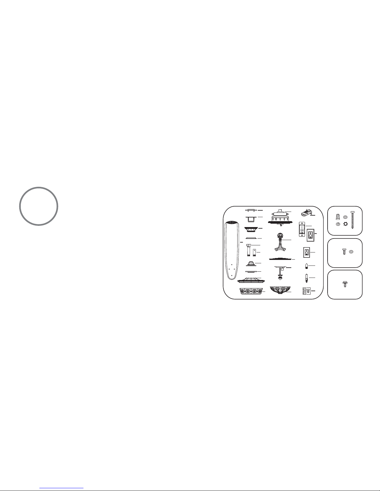
1. Fan blades (5)
2a. Hanger bracket plate
2b. Hanger bracket
3. Canopy
4. Canopy cover
5a. Standard downrod assembly
5b. Minimum-length downrod
(for close to ceiling mounting only)
6. Coupling cover
7. Top plate cover
8. Motor housing cover
9. Glass housing
10. Fan motor/housing assembly
11. Blade holders (5)
12. Mounting plate
13. Light plate
14. Glass shade
15. Receiver with 7 wire nuts
16a. Wall transmitter Incl. 2 mounting
screws and 3 wire nuts
16b. Wall plate w/2 mounting screws
17. Extra Wall Plate w/2 Mounting screws
18. 15 Watt candelabra bulbs (5)
19. 50W Halogen bulbs (2)
20. Balancing kit
A. Mounting hardware:
#14 X 3.5" Wood sscrews (2 PCs.)
Star washers (2 PCs.)
Lock washers (2 PCs.)
Washers (2 PCs.)
Wire nuts (3 PCs. )
B. Blade attachment hardware:
3/16" x 10 mm Screws (21 PCs.)
Fiber washers (21 PCs.)
C. Bracket holder hardware:
1/4" x 1/2" Screws with lock washers (11 PCs.)
PACKAGE CONTENTS
Unpack your fan and check the contents.
You should have the following items:
3
1
2a
2b
5a
5b
18
17
19
20
15
16a
16b
4
6
7
8
9
10
11
12
13
14
A
B
C
3
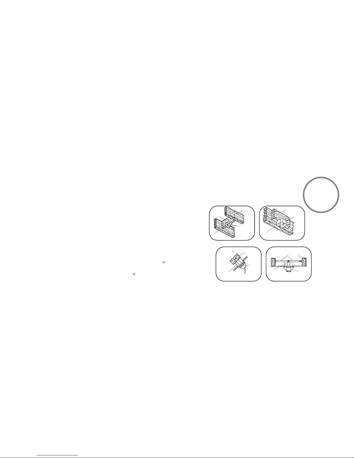
INSTALLING THE FAN
FIG. 1
FIG. 3
FIG. 2
FIG. 4
CROSS BRACE
CEILING
JOIST
CEILING
jOIST
CEILING
JOIST
OUTLET BOX
PARALLEL WOOD BRACE
(MIN. 2" THICK)
OUTLET
BOX
OUTLET BOX
CEILING JOIST OR
CROSS BRACE
ANGLED CEILING
MAXIMUM 29 ANGLE PROVIDE
STRONG
SUPPORT
RECESSED
OUTLET BOX
HANGER
OPENING
must be
FACING
UPSIDE
HANGER BAR
(OPTIONAL)
HANGER
BRACKET
Tools Required: Phillips screw driver; slotted screw driver; step-ladder; wire cutters; electrical tape.
MOUNTING OPTIONS
If there isn't an existing mounting box,then read the following instructions.Shut the power off
at the circuit breaker or fuse box.
NOTE: THIS CEILING FAN EXCEEDS THE MAXIMUM WEIGHT SPECIFIED BY UL FOR HANGING
FROM A STANDARD OUTLET BOX. SPECIAL REINFORCEMENT OF THE CEILING IS REQUIRED
FOR INSTALLATION.
Secure the ceiling fan's hanging bracket directly from the building structure via the outlet box.
Figures 1,2 and 3 are examples of different ways to mount the outlet box.
Note:You may need a longer downrod to maintain proper blade clearance when installing on a
steep,sloped ceiling. Longer downrods are available from your Minka-Aire dealer.
To hang your fan where there is an existing fixture but no ceiling joist,you may need to install a
hanger bar as shown in Fig. 4 (available at your Minka-Aire dealer).
R
R
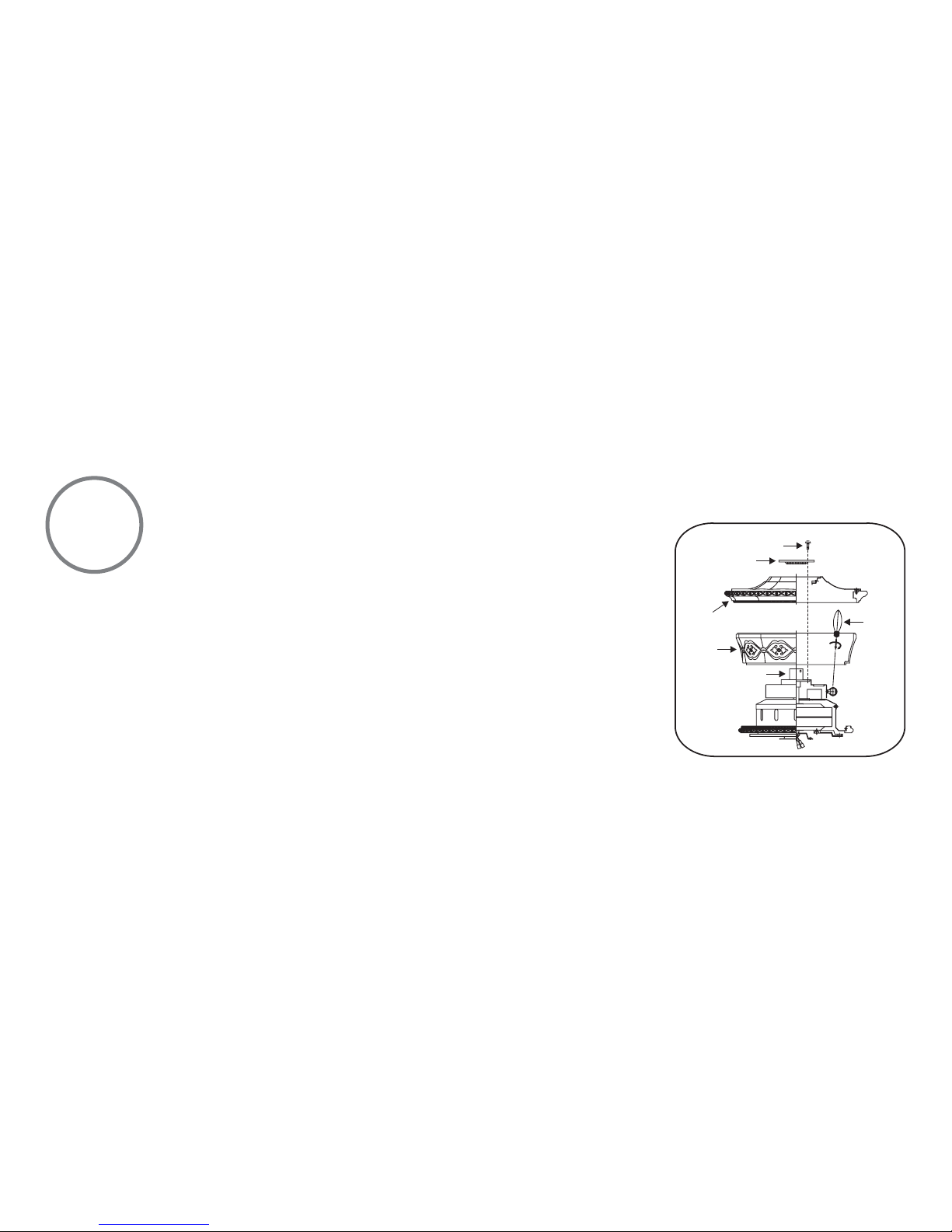
4
Step 1. Remove three of the six screws and lock washers (every other one) from the collar of top
motor (Figure. 5)
Step 2. Place the glass housing onto the motor assembly, install the 5 x 15W bulbs (provided) into
the bulb holder assembly. Then place the motor housing cover onto the glass housing, followed by
the top plate cover, replace the three screws previously removed and securely tighten. (Figure. 5)
Fig. 5
MOTOR HOUSING ASSEMBLY
SCREWS
COLLAR
BULBS
TOP PLATE
COVER
MOTOR HOUSING COVER
GLASS
HOUSING
Ce manuel convient aux modèles suivants
7
Table des matières


