SAMUEL JACKSON Argus Manuel utilisateur

!!
Installation!and!Resource!Guide

!
!
!
!
!
!
!
!
!
!
!
!
!
!
!
!
!
!
!
!
!
!
!
!
!
!
!
!
!
!
!
!
!
!
!
!
!
!
!
!
!
!
!

TABLE OF CONTENTS
Argus Installation and Resource Guide
1
1.0 COMPONENTS
1.1 DETECTORS 2
1.2 CONTROL PANEL 3
1.3 POWER CARD 4
1.4 ZONE CARD 6
1.5 ALARM/MONITOR CARD 8
1.6 HORN/STROBE LIGHT 10
2.0 INSTALLATION
2.1 DETECTOR PLACEMENT 11
2.2 INSTALLING DETECTORS 12
2.3 MOUNTING THE PANEL AND SUPPLYING POWER 13
2.4 WIRING ZONE CARDS/DETECTORS 14
2.5 WIRING RELAYS 15
2.6 WIRING HORN/STROBE 16
2.7 TESTING FOR GROUND FAULT 17! !
3.0 START-UP PROCEDURE
3.1 TESTING DETECTORS 18
4.0 OPERATION
4.1 WHAT TO DO IN A SPARK DETECTION SCENARIO 19
5.0 MAINTENANCE
5.1 LENS REPLACEMENT 20
5.2 ROUTINE MAINTENANCE 22
5.3 TROUBLESHOOTING 23
6.0 INSTALLATION GUIDE
6.1 DETECTOR INSTALLATION GUIDE 26
6.2 ELECTRICAL WIRING DIAGRAM 35
7.0 WARRANTY
7.1 WARRANTY 36
!
!

COMPONENTS
Argus Installation and Resource Guide
2
1.0 COMPONENTS
1.1 DETECTORS
The heart of the Argus fire detection is the spark detector. The detector is equipped with
a lens that can see infrared light emitted by extremely small sparks and warn you before
they have a chance to become a fire.
There are two types of detectors, the 343 and 535.
As of 2014 only the 535 detector is available for sale, and all orders for Argus will
include the 535 detector only. Although there are a few changes between the two
detectors, they operate identically. This means that if you choose to replace one of the
old 343 detectors in your gin with a new 535 one, the zone you modified will still work
as before.
The changes between the 343 and 535 detectors that you should be aware of are:
•Mounting dimensions are different. When replacing old detectors, new holes must be
drilled for the mounting brackets.
•The 535 detector has a two-tone LED that indicates whether detector is in an alarm
state (red) or standby (green).
•The End-of-line (EOL) module required for the 343 detector is no longer needed for
the 535. Instead, there is a switch on the 535’s circuit board that should be toggled in
the last detector in a zone. For more information about zone card/detector wiring,
please refer to section 2.4.

COMPONENTS
Argus Installation and Resource Guide
3
1.2 CONTROL PANEL
The control panel houses all the electronics, including the power card, monitor card, zone
cards, and relays. It should be in an accessible location near the gin’s console for easy
access in case of a fire.
The 10-zone panel pictured contains one power card, one monitor card, and room for ten
zone cards.

COMPONENTS
Argus Installation and Resource Guide
4
1.3 POWER CARD
The power card is housed in the top-left slot of the panel and has four indicator lights.
The indicators and adjustments are listed below, some of which are not applicable to
cotton gins. Also included is information on power supply fusing.
•AC Power Indicator (AC Power) on panel door (28 volt bulb): Normally "ON" unless
AC power fails or the bulb fails.
•LED-1 green DC Power Indicator (PWR): Normally "ON" unless fuse F-1 blows (as
long as the battery is connected to the system and fuse F-2 is in the circuit)
•LED-2 green Battery Charged Indicator (CHGD): Not applicable to cotton gin uses.
•LED-3 amber Battery Discharging Indicator (DISCH): Not applicable to cotton gin
uses.
•LED-4 amber Battery Charging Indicator (CHNG): Not applicable to cotton gin uses.
•P-2 Voltage Regulator (Potentiometer): Adjust for 24 volts DC +/- 0.1 volts (measure
across detector output terminals pins 1 & 3) with maximum load on system. Not
applicable to cotton gin uses.
•P-1 Battery Charging Voltage Regulator (Potentiometer): Not applicable to cotton gin
uses.
•SH1 Battery “YES/NO” Indicator: Jumper should be placed on pins towards desired
side.
NOTE: For cotton gin applications, make sure the black jumper is placed on the
pins on the NO side.
Figure: Power Card

COMPONENTS
Argus Installation and Resource Guide
5
Power Supply Fusing:
•F-1 – Battery Charging Fuse (AGC 5 Amperes): This fuse passes both the regulated
and unregulated current when the system goes into battery mode operation. It must
pass current for extinguishers as well as detectors thus it is sized to allow system
operation in event of power disruption. Not applicable to cotton gin uses.
•F-2 – Regulated Power Fuse (GMA 2 Amperes): This fuse controls the regulated 24
volts DC supplied to the circuit boards and detectors. The 2 amperes rating is the
maximum fuse rating for fuses used in this position. Systems with few detectors
and/or zones can use fuses of lesser ratings. Fuses should always be sized to fit the
application or demand current.
•Primary Fuse (GMA 5 Amperes): The primary fuse is located in the AC line
supplying current to the transformer used in the system. The transformer used and the
system configuration or size predicates its size. This fuse passes the entire AC current
demand for the system through a 5 to 1 step-down transformer when a 120 volts AC
line is used. In addition, this fuse must be sized to blow in the event of transformer
failure and/or bridge filter capacitor failure. Typically, the fuse should be a fast blow
5 amperes maximum fuse for maximum power when using a 4 amperes transformer
(120 volts AC to 24 volts DC). The fuse should have a 1 ampere rating when used
with 240 volts AC to 24 volts DC, 4 amperes transformers.

COMPONENTS
Argus Installation and Resource Guide
6
1.4 ZONE CARDS
Each set of detectors is wired to its own zone card located in the control panel. For
information on wiring zone cards, see section 2.4. This section includes a brief overview
of the LED indicators, switches, and fuses located on the card.
Indicators
•LED #1 – green Power Indicator (PWR): Indicates the presence of 24 volts DC
regulated voltage from the power supply regulator.
•LED #2 – red Alarm Indicator (ALM): Indicates an activation of the alarm circuitry
by the detector.
•LED #3 – amber Detector Trouble Indicator (DET): Indicates trouble in the external
circuits to and from the detector. It will illuminate when the reset switch is operated.
•LED #4 – amber Extinguisher Trouble Indicator (EXT): Indicates trouble in the
extinguisher firing circuit, such as extinguisher disconnect switch being in the open
position, a fuse is blown, open leads, etc.
Switches
•Reset Switch: a normally closed, momentary switch that controls 24 volts DC to the
detectors connected to the zone.
•When operated (moved to the “UP” position), it disconnects the 24 volts DC power
from the detectors, which automatically reset themselves. While operated the amber
indicator will flash and the trouble alert will beep.
Figure: Zone Card

COMPONENTS
Argus Installation and Resource Guide
7
•Extinguisher Disconnect Switch: This switch disconnects the extinguisher and relay
circuits to allow for maintenance. When this switch is in the “UP” position, the
extinguisher amber indicator (EXT) will blink and the trouble alert will beep (unless
silenced) until the switch is returned to the normal “DOWN” position.
Fusing
•The fuse marked F-1 (2 amp) should not be sized greater than 2 amperes.
•Should this fuse blow, the extinguisher and relay power is disconnected and the
amber Extinguisher Trouble Indicator (EXT) will blink.
•Current limiting is provided on the unsupervised relay (terminals 5 and 6) and AUX
relay terminals (8 and 9). The maximum current that will be supplied to these
terminals is 250mA total for the two relays. Current in excess of this amount will shut
down the driving circuit without causing damage to the unit or malfunction of the
alarm circuits.
COMPONENTS
Argus Installation and Resource Guide
8
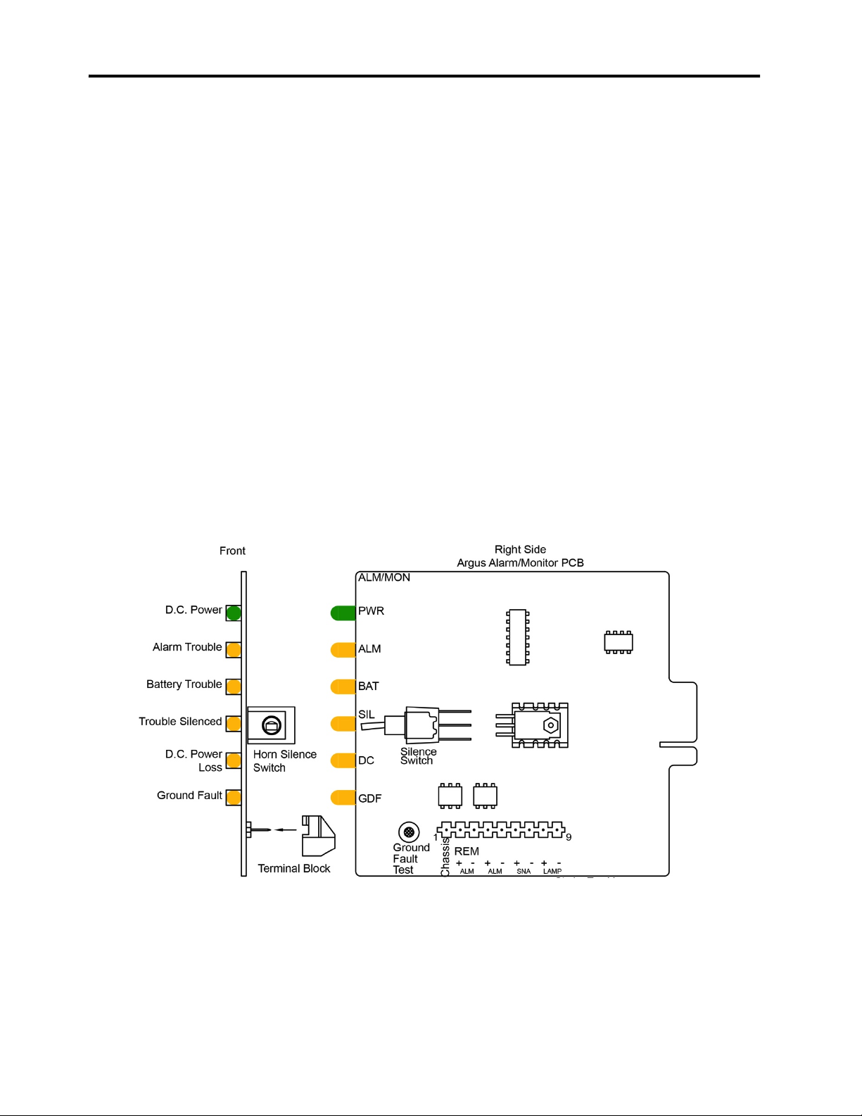
1.5 ALARM/MONITOR CARD
The Alarm/Monitor card indicates whether the system is working properly or not. If
none of the amber LEDs are lit, then the system should be working properly. This
section goes over the function of each LED and the silence switch.
Indicators
•LED #1 green DC Power Indicator (PWR): Indicates regulated 24 volts DC on card
when illuminated.
•LED #2 amber Alarm Trouble Indicator (ALM): Indicates trouble in the primary
alarm bell circuit.
•LED #3 amber Battery Trouble Indicator (BAT): Indicates battery not in system, SH-
1 on Power Supply Card not in circuit to selected battery, or non-battery operation.
•LED #4 amber Silence Switch Trouble Indicator (SIL): Indicates trouble silence
switch “ON” in 24 v DC circuit on card or ribbon cable.
•LED #5 amber DC Power Trouble Indicator (DC): Indicates trouble in 24 volts DC
circuit on card or on ribbon cable.
•LED #6 amber Ground Fault Trouble Indicator (GDF): Indicates ground fault in
system during installation. This is an installation aid. The system is normally
grounded when operational.
Figure: Alarm/Monitor Card
Table des matières
Manuels Détecteur de fumée populaires d'autres marques


System Sensor
System Sensor DH500ACDC Manuel utilisateur

Resolution Products
Resolution Products RE612 CryptiX Manuel utilisateur

First Alert
First Alert PC900V Manuel utilisateur

Eminent
Eminent EM6590 E-Domotica Manuel utilisateur

Ei Electronics
Ei Electronics Ei Ei168RC Manuel utilisateur

Carrier
Carrier Kidde Quell Q301 Manuel utilisateur


