Sakura SRT-30RA Manuel utilisateur
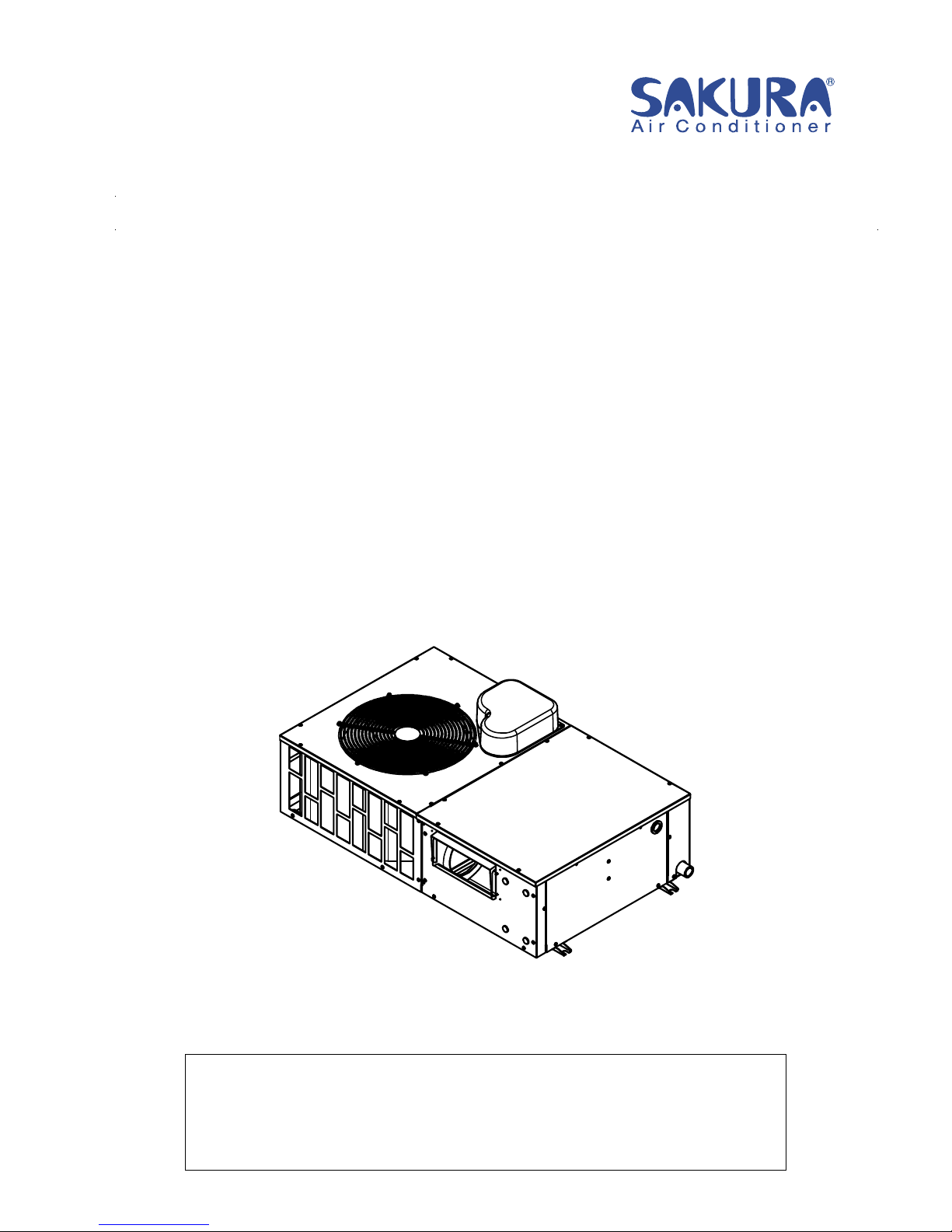
ROOFTOP PACKAGE AIR CONDITIONER
INSTALLATION MANUAL
This manual provides the procedures of installation to ensure a safe and good standard of
operation for the air conditioner unit.
Special adjustment may be necessary to suit local requirements.
Before using your air conditioner, please read this instruction manual carefully and keep it for
future reference.
SRT-30RA
Page 1 of 15
FEATURES
Electro Galvanized Steel Panels
Corrosion Resistant Cabinet - The weather proof characteristics of the panels have been significantly
reinforced by the adoption of electro galvanized steel panel which have been coated with polyester powder
coated paint to resist corrosion.
Protection System
Compressor Protection - The compressor is protected with high pressure switch, an over current relay,
an internal overload protector.
Fan motor - The evaporator fan motor and outdoor fan motor are protected with internal overload
protector.
Condenser and Evaporator Coil - The coil have seamless Inner groove copper tubing mechanically
bonded to high efficiency. Each coil is factory tested at 600 psig. And easily accessible for service.
SAFETY PRECAUTIONS
Before installing the air conditioner unit, please read the following safety precautions carefully.
Warning
•Installation and maintenance should be preformed by qualified persons who are familiar
with local code and regulation, and experienced with this type of appliance.
•All field wiring must be installed in accordance with the national wiring regulation.
•Ensure that the rated voltage of the unit corresponds to that of the name plate before
commencing wiring work according to the wiring diagram.
•The unit must be GROUNDED to prevent possible hazard due to insulation failure.
•All electrical wiring must not touch the refrigerant piping, compressor or any moving parts
of the fan motors.
•Confirm that the unit has been switched OFF before installing or servicing the unit.
•Do not touch the compressor or refrigerant piping without wearing gloves.
Caution
Please take note of the following important points when installing.
-Do not install the unit where leakage of flammable gas may occur.
If gas leaks and accumulates at the surrounding of the unit, it may cause fire ignition.
-Ensure that the drainage piping is connected properly.
If the drainage piping is not connected properly, it may cause water leakage.
-Do not overcharge the unit.
This unit is factory full charged. Overcharge will cause over-current or damage to the
compressor.
-Ensure that the unit panel is closed after service or installation.
Unsecured panels will cause the unit to operate noisily.
Page 2 of 15
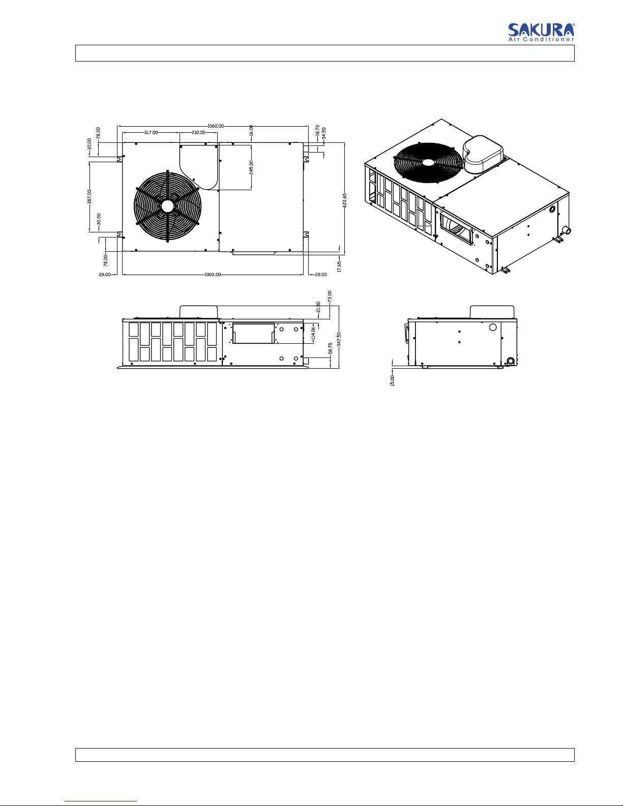
OUTLINE AND DIMENSIONAL DATA
SRT-30RA
NOTE: “Standard marking on the cover applicable to specific models; check with label data on the unit.”
Page 3 of 15
INSTALLATION OF THE UNIT
Location For Installation
Install the unit in such way that air distributed by the unit cannot be drawn in again (as in the case of
short circuit of discharge air). Allow sufficient space for maintenance around the unit.
Ensure that there are no obstructions of air flow into or out of the unit. Remove obstacles which blocks
air intake or discharge.
When two or more outdoor units are installed in a location, they must be positioned such that one unit
will not be taking the discharge air from another.
The location must be well ventilated, so that the unit can draw and distribute plenty of air.
A place capable of bearing the weight of the outdoor unit and isolating noise and vibration.
A place protected from direct sunlight. Otherwise use an awning for protection, if necessary.
A place where smooth drainage of rain water and water formed by defrosting is acceptable.
A place where the unit will not be buried in snow.
A place where air outlet port is not exposed to strong wind.
A place where the air discharge and operating sound level will not annoy the neighbors.
The location must not be susceptible to dust or oil mist.
Caution
If the condensing unit is operated in an atmosphere containing oils (including machine oils), salt
(coastal area), sulfide gas (near hot spring, oil refinery plant), such substances may lead to failure of
the unit.
Page 4 of 15
INSTALLATION OF THE UNIT
Unit Support
1. The figure shows the use of the roof curb available for mounting these units.
2. The curb should be sealed and fixed to the roof by weather stripping. A suggested means of sealing
the unit and roof curb as shown in the left.
Duct construction
-These units are equipped with supply and return air openings. Duct connection to the unit
should be made with duct flanges and secured directly to the air opening with flexible duct
connectors to avoid normal noise transmission.
-To prevent air leakage, all duct seams should be sealed.
-Ducts in the spaces that not air-conditioned, must be insulated.
-Ducts exposed to the outside must be weather proofed.
-Ducts that entering building through the roof, the entering should be sealed with weather
stripping to prevent the rain, sand, dust etc. from entering the building.
-Correct size of filter must be installed at the return air duct.
Refrigerant Charge
The units are full charged in Factory, no additional charge is necessary. The table below shows the
amount charged pre unit.
Refrigerant R-410A
Model Charge in circuit (kg)
SRT-30RA 1.35
INSTALLATION OF THE UNIT
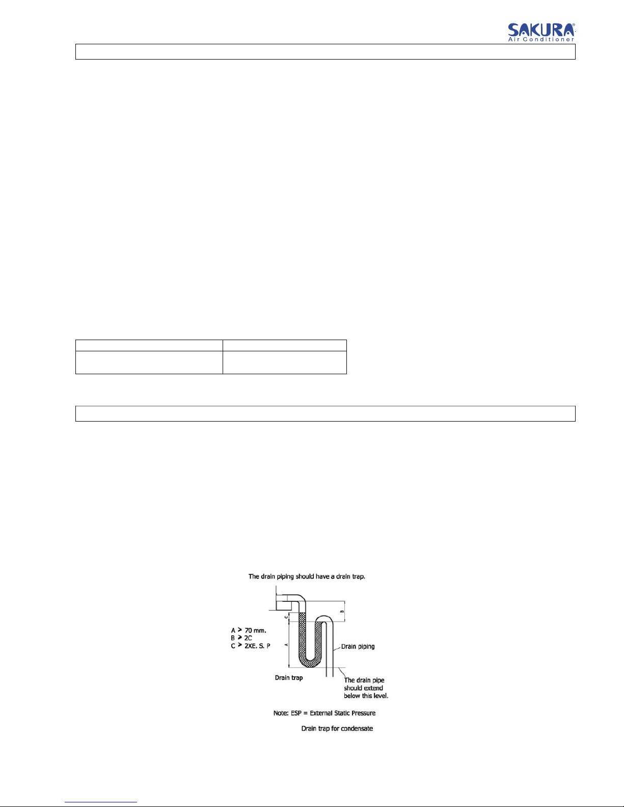
Drain piping
-A 1 MPT condensate drain fitting is provided. The drain pipe can be led out at the front side.
-The drain pipe must be provided with a trap on the outside of the unit and also installed at an
incline for proper drainage, as shown in the right.
-To prevent condensate formation and leakage, provide the drain pipe with insulation to
safeguard against sweating.
-Upon completion of the piping work, check that there is no leakage and that the water drains
off properly.
Page 5 of 15
Control System & Electrical Wiring
Function and Specification
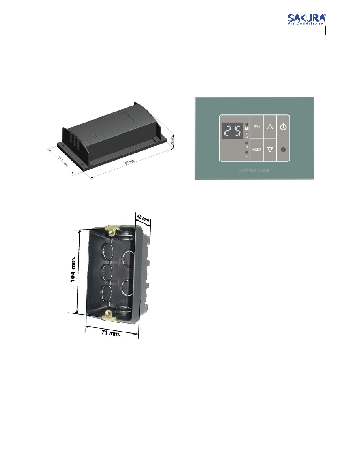
1. Major component
-. Main unit
-. Display unit
-. Display cable 2 cores, length 4 metres between Main unit and Display unit
-. Flush-mounted box
Main Unit Display Unit
Flush-mounted box
Page 6 of 15
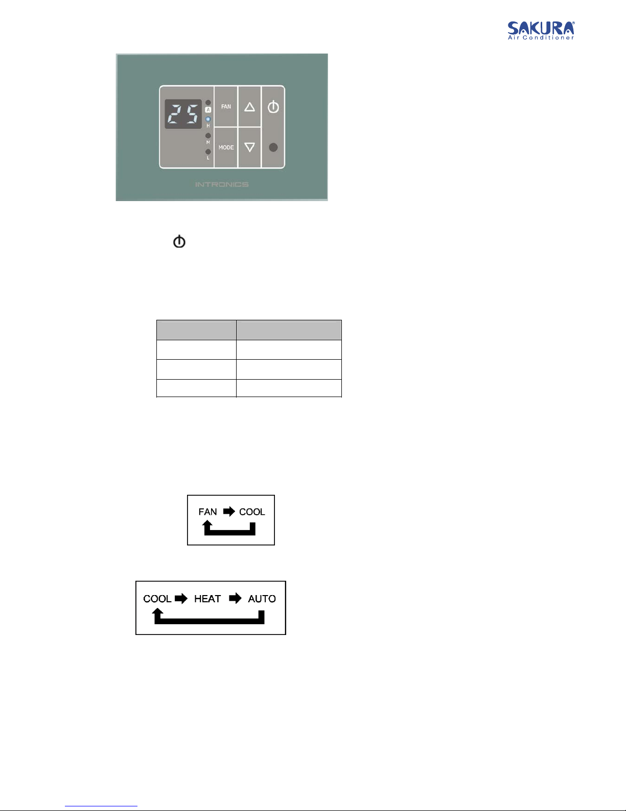
2. User’s Features
2.1 Power on/off
Push button to on or off unit
2.2 Fan speed
Push button FAN to change fan motor speed. (High, medium, low or auto) In AUTO FAN operation mode,
fan motor speed will be change automatic according to the difference temperature gap between Troom &
Tset. (ΔT)
2.3 Operation mode
Push button MODE, system will operate as below
? 2 Operating modes (fan, cool) In case of COOL version
? 3 operation modes (fan, heat, cool) In case of Heat/Cool version
Note : In case of remote control utilization, it can be set mode in 5 mode (Fan, Cool, Dry, Heat,
Auto)
FAN : Air conditioner will operate as fan only. (Compressor will not work) And in this mode, it can’t use
SLEEP mode and it can’t set temperature while there is no temperature display on remote control.
COOL : Air conditioner will operate as cooling by room temperature higher than setting temperature and
compressor operation stop working more than 3 minute, compressor will operate again to decrease
room temperature.
∆T Speed
> 3°C high
= 2°C medium
< 1°C low
Page 7 of 15
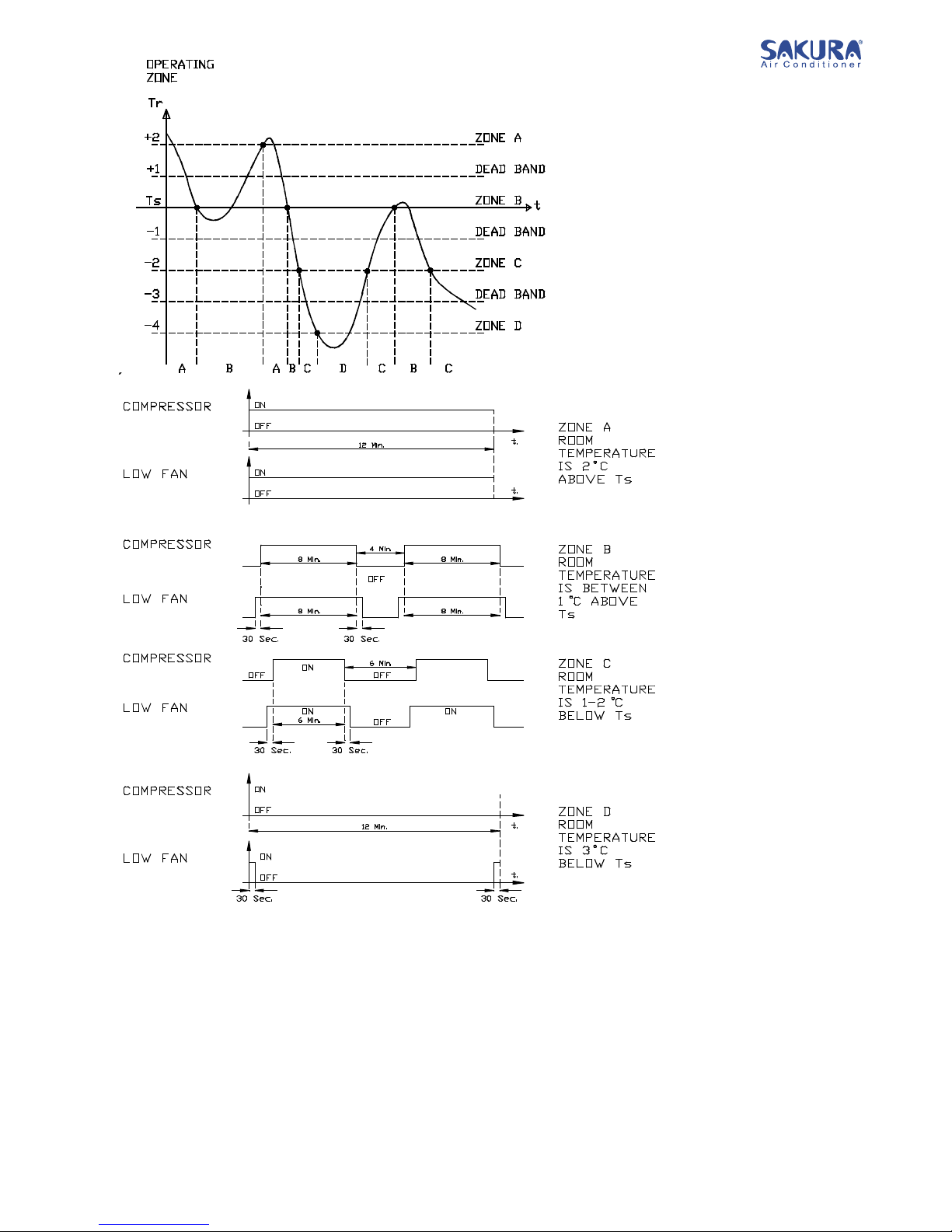
Dry : Air conditioner will operate to reduce
room humidity. The operation in DRY
MODE will be separate in to each
ZONE which are ZONE A, B, C, and D
as below.
Zone A : Room temperature range is
higher than setting temperature for 2°C.
Zone B : It will be operated in room
temperature range equal to setting
temperature or temperature gap is
lower than 1°C.
Zone C : Room temperature range is
lower than setting temperature for 1-2°C
Zone D : Room temperature range is
higher than setting temperature for 3°C.
Exclude temperature
range which are in range
of Zone A & Zone B,
Zone B & Zone C and
Zone C & Zone D, these
call DEAD BAND. These
Zones have stability
which is no changing
Zone in these
temperature ranges.
Page 8 of 15
Zone calculation will be determined in every 12 minutes which is one operating cycle in DRY MODE and
the operation of compressor and fan motor while in each ZONE has show in the picture. By fan motor will operate
before compressor starting for 30 seconds and fan motor will stop operation after compressor stop for 30 seconds.
In DRY MODE, we can’t use SLEEP function or change speed of fan motor by there is no show fan motor
speed on remote control
HEAT : Air Conditioner will operate as heater which call HEAT PUMP
When system operated as HEAT PUMP, controlling system will reverse refrigerant cycle by open
REVERSING VALVE to make air conditioner work as heater. When room temperature is lower than setting
temperature and compressor has stopped working more than 3 minute, compressor will operate to increase room
temperature.
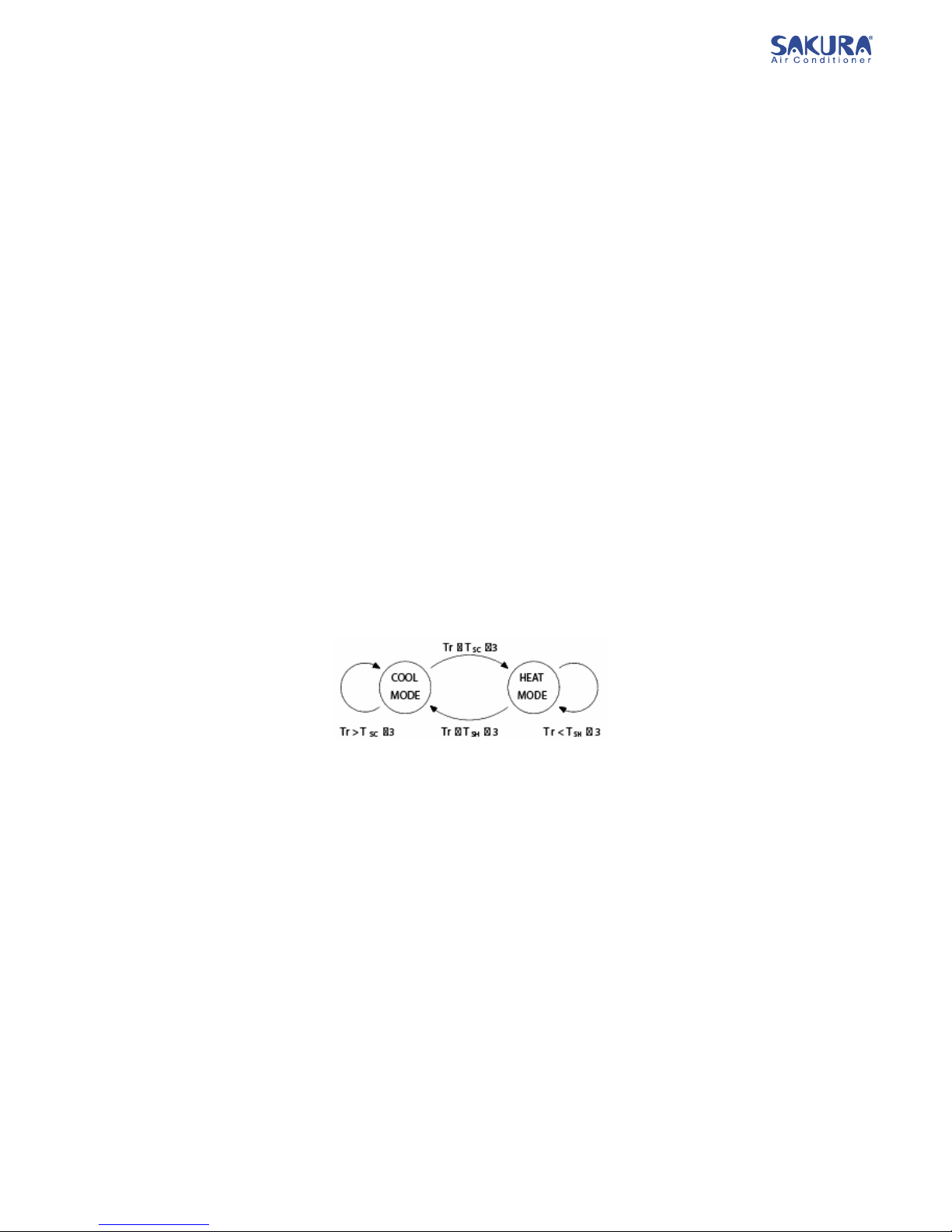
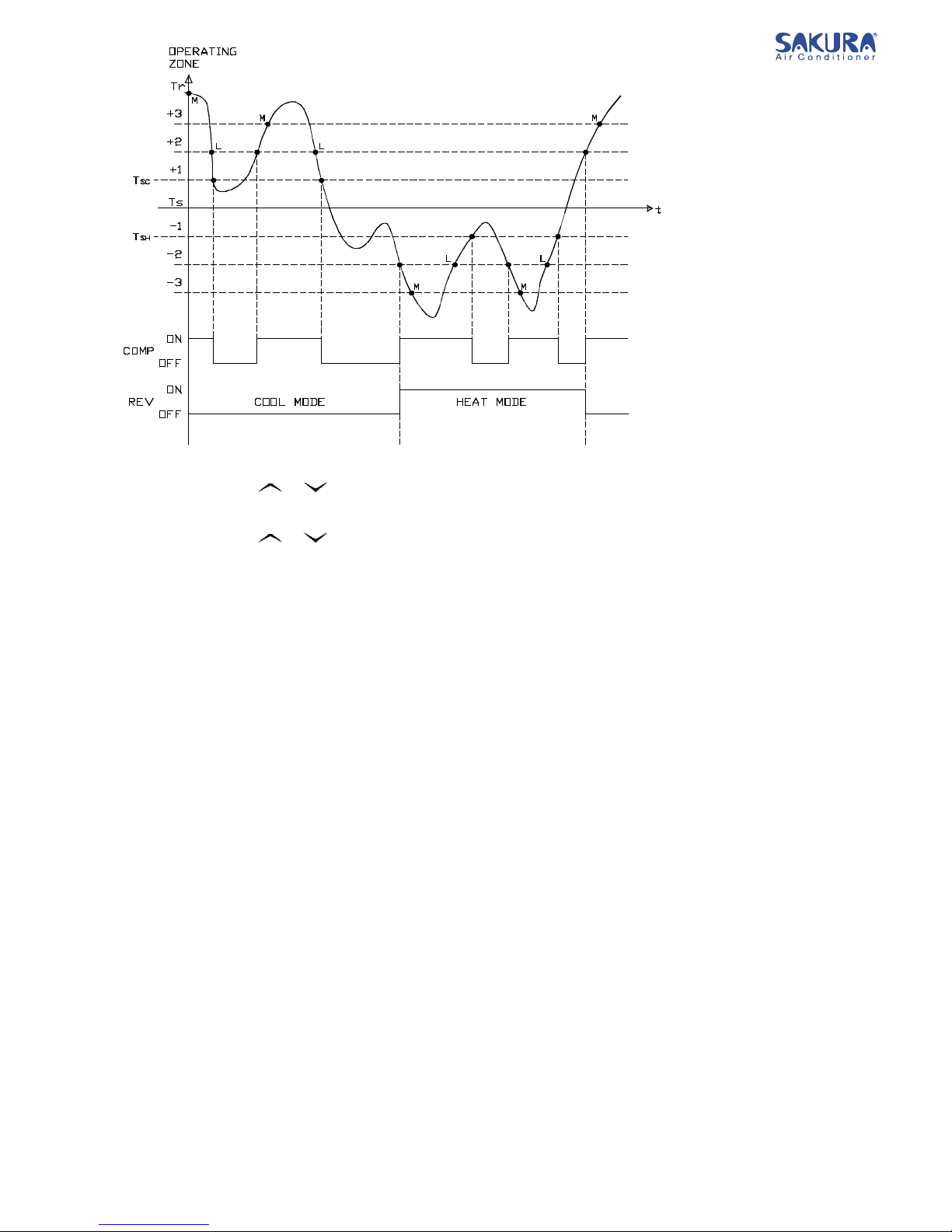
AUTO : Air conditioner operate by controlling system will choose operating system to be COOL or HEAT
automatically. It depend on setting temperature and room temperature at that time.
While operating as COOL MODE, setting temperature will simply increase 1°C from setting temperature on
remote control. It will use this value as setting temperature to calculate other value.
Tset working in Cool (TSC) = Tset actual + 1°C
While operating as HEAT MODE, setting temperature will simply decrease 1°C from setting temperature on
remote control. It will use this value as setting temperature to calculate other value.
Tset working in Heat (TSH) = Tset actual - 1°C
While operating as COOL MODE, it will change to HEAT MODE when room temperature at that time is
lower than Tset working in Cool (TSC) from 3°C below. And while operating in HEAT MODE, it will change to COOL
MODE when room temperature at that time is higher than set working in Heat (TSH) from 3°C upper.
Page 9 of 15
2.4 Temperature setting
Push button or to change Setting temperature from 18-30°C
2.5 Dim
Push button or by holding for 3 seconds to reduce the intense of LED light. When turn off air
conditioner, the intense of light will change to be normal
2.6 Remote Handset
Can use function in remote control as usual such as SLEEP, TIMER
3. SYSEM FEATURES
3.1 Watchdog : In controlling system, when system error according to computerized system which may come
from unstable of electrical voltage or from noise, system will set computer to reset immediately.
3.2 Compressor delay protection : In case of compressor stop operation, it always delay time before restart
again for 3 minute. And in case of electric shut off from system and resupply again, it will delay operating of
compressor for 3-4 minute by randomly.
3.3 Compressor minimum on time : compressor always have to operate at least 24 seconds before stop
operation.
3.4 Auto restart : In case of electric shut down, when electricity restart as normally, system will operate
according to last setting program except SLEEP and TIMER that will be cancelled by value will keep record
in MEMORY after changing in value at least 5 seconds. So if the changing in value does not reach 5
seconds before electric shutdown, when system restart, it will operate according to memory value before
changing.
3.5 Freeze protection : In Cool or Dry mode, if T indoor coil ≤ 0°C and compressor has been operating at least 10
minutes continuously. Freeze will occur. System will stop compressor operation and fan speed will operate
in low.
System will return to operate as normally when T indoor coil ≥ 7°C or turn off product.
3.6 Defrost function : In Heat mode, if T outdoor coil has low value compressor will operate as in effective way.
Defrost function will help to protect compressor from damaging.
Table des matières
Autres manuels Sakura Climatiseur

Sakura
Sakura COOLING ONLY Manuel d'instructions

Sakura
Sakura FCR Manuel utilisateur

Sakura
Sakura FVCA Series Manuel utilisateur

Sakura
Sakura HBK-23DL Manuel

Sakura
Sakura HBK-18?23DS Manuel

Sakura
Sakura SFP KM EC Series Document technique

Sakura
Sakura SFP-KM-DLY Series Manuel utilisateur

Sakura
Sakura FASN 080-600 Manuel utilisateur


