Safe Fleet RVS-130 Manuel utilisateur

Advanced Blind Spot Sensor System
RVS-130
Instruction Manual
VEHICLE SAFETY -
IT'S ALL WE DO.
TM

Rear View Safety
2
ItemList....................................02
TechnicalSpecication..............................03
Wiring Diagram...............................03-04
WireConnectionDiagram.......................... . 04
InstallationGuide.. ............................05-07
AlertConditions.................................07
Alert Characteristics. . . . . . . . . . . . . . . . . . . . . . . . . . . . . . 08
Troubleshooting . . . . . . . . . . . . . . . . . . . . . . . . . . . 09
Customer Service Bulletin. . . . . . . . . . . . . . . . . . . . . . . . . . . . . . . . 10-11
SafetyInformation........................ . . . . . 12
Warranty........................... . . . . . 13
Disclaimer........................... . . . . . 14
TheRVSDierence......................... . . . . . 15
TABLE OF CONTENTS
Radar Sensor
2PCS
Sensor Extension Cable
2PCS (one red one yellow)
GPS Antenna
1PCS
LED Extension Cable
2PCS (one red one yellow)
LED Indicator
2PCS
Buzzer
1PCS
Main Unit
1PCS
Main Harness
1PCS
3M Velcro
4PCS
Item List
Tools for installation: insulation tape,
multi-meter, screwdriver, cleaning cloth, tape.

Reverse With Condence ™ 3
TECHNICAL SPECIFICATION
Technical Specication
Wiring Diagram
Operating frequency
Transmit power
Detection range
Detection ability
24.0 ----24.25GHZ
15dbm
40 degree (Horizontal )
5 targets can be detected at the same time
Speed range 0.35mph---137mph
Speed accuracy < 0.35mph
Direction of movement
Speed Restriction
Detection range
Approached or overtaken by vehicles
Car: 1ft-50ft
Motorcycle:1ft-33ft
Pedestrian:1ft-23ft
Operating voltage
cables waterproof
9---35V
Radars: IP 67 / Cables: waterproof
Working current
Working temperature
< 200mA
-40℃~ + 85℃
1.The GPS Antenna when connected activates
notications over 20mph (Example LED + Speaker)
2.If No GPS signal is detected or satellites not found,
the system will give notications at any speed.
LED
Buzzer
LED
R-SENSOR
L-SENSOR
M ain Unit

Rear View Safety
4
LED
LED
R-SENSOR
L-SENSOR
M ain Unit
LED
LED
R-SENSOR
L-SENSOR
M ain Unit
WIRE CONNECTION DIAGRAM
Buzzer
Buzzer
Wire Connection Diagram

Reverse With Condence ™ 5
INSTALLATION GUIDE
Installation Guide
Step 1. Sensor Installation
Installation requirements: Sensors should be mounted on the widest part of the
vehicle and as far forward as possible, Using screws to x the sensor on the front
of the vehicle.
Step 2. Installation of the left/right turn trigger.
Using the voltage Multi-meter, locate the left
and right turn signal trigger wires behind the
front turn signals. Once veried, connect the
left and right signal wires of the RVS-130 wire
harness to the correct signal wires.
SCREW
SENSOR HOUSING
L - Left Sensor
R - Right Sensor

Rear View Safety
6
Step 3. LED Indicator Installation
Place the LED indicators where it is visible for the driver. Ideally on the A-pillar.
Step 4. Buzzer Location
Ensure speaker is installed in accessible area to allow driver
access to volume controls.
L - Left LED R - Right LED
Buzzer
Step 5. Tuck the wires neatly to hide and prevent wire pinch.
INSTALLATION GUIDE

Reverse With Condence ™ 7
ALERT CONDITIONS
Illumination of the LED indicator on the control box:
1.The LED comes on solid when the system is rst powered up;
2.The LED blinks slowly while the GPS module is connected to the satellite;
3.The LED blinks quickly while sensing moving objects approaching in the blind spot
(same frequency as to the alarm LED indicators & the buzzer);
4.The LED maintains the last blinking status after the alerts have ended
(the last blinking status of alarming is o / on randomly)
Step 6. Main Unit Location
While installing the main box, use tape to securely fasten it in place.
When the vehicle is on, the system
should detect objects that are over-
taking your vehicle in the lane next
to your vehicle up to 50 ft. to the rear.
NOTE!
Alert Conditions

Rear View Safety
8
A. Blind detection on right side:
1. R-LED indicator will be activated when there is an object approaching to the
right side blind area of your vehicle (see Fig.16).
2. If the right turn signal of your vehicle is triggered at the same time, the R-LED
indicator will be blinking and the buzzer will be beeping as well (with the same
frequency).
B. Blind detection on left side:
1. L-LED indicator will be activated when there is an object approaching to the
left side blind area of your vehicle (see Fig.16).
2. If the left turn signal of your vehicle is triggered at the same time, the L-LED
indicator will be blinking and the buzzer will be beeping as well (with the same
frequency).
C.The LED and buzzer will standby (no activity) if there is no object approaching
to the blind area of your vehicle.
D. During reversing, the R & L LED will be blinking according to the approaching
object detection of each side.
INSTALLATION GUIDE
Alert Characteristics

Reverse With Condence ™ 9
TROUBLESHOOTING
Troubleshooting
Issue Reason Solution
LED light does not
work
Opposite LED
indicator
Buzzer does not work
Unit does not work
after GPS is connected
Sensors or GPS does
not work
Incorrect connection or pins not
making contact
LED light is broken
Microwave sensor or LED
indicators are plugged in to the
opposite connector
Defective buzzer speaker
Sensors or GPS module are
covered by the metal bumper or
other metal
Sensors or GPS module are
covered by the metal bumper or
other metal
Blind spot system does not
trigger the sensors if the speed is
less than 20mph
Find the best location where the
GPS antenna cannot be blocked
by any metal
Replace buzzer
Wrong connection or pins not
making contact
Check the harness and make sure
connection is correct
Make sure RED is driver side and
YELLOW is passenger side.
Replace LED light
Check the harness and make sure
connection is correct
8

Rear View Safety
10
Summary
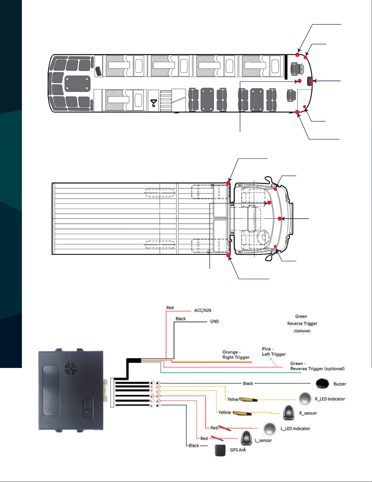
This bulletin addresses three solutions to the issue of false alarms
with the RVS-128, RVS-129, RVS-130:
• Sensor's orientation.
• Large surface anomalies in the sensor eld of view.
• Use of steel screws in conjunction with the environment, resulting in reections to the sensors.
Issue
Occasionally, when the system is installed and tested, there are constant false alarms as the vehicle
is moving even where there are no other vehicles in the area.
Solutions
Here are three additional possible causes and their solutions.
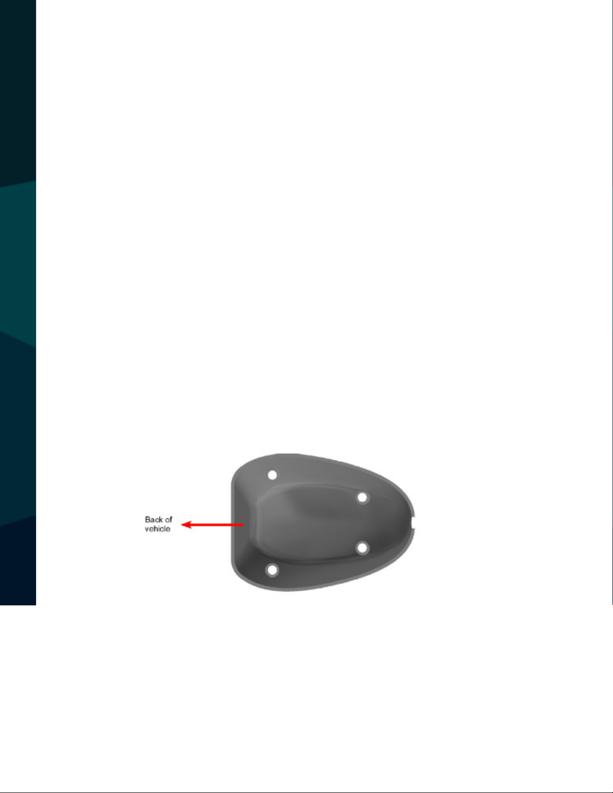
Wrong orientation
Change orientation 180°. The sensor should be oriented with the at bottom attached to the
vertical side of the vehicle, perpendicular to the ground.The large end of the sensor should be
directed toward the back of the vehicle.
CUSTOMER SERVICE BULLETIN
Customer Service Bulletin
Why incorrect orientationisa problem:Themicrowave signalisemittedout of thelargerend ofthe
sensor. The sensor will sense objects coming toward it. So, if it is pointing in the wrong direction,
it may sense things that are stationary, such as trees, as moving toward it. This is especially seen
whenthesensor ispointingtowardthe front of thevehicle(allstationaryobjectswouldbemoving
toward the sensor and cause false alarms).
CSB00101 Aected Products: RVS-128, RVS-129, RVS-130.
Table des matières


