Saab 12 832 505 Manuel utilisateur
Saab 9-3 CV M04-
900 Installation instructions
SCdefault
MONTERINGSANVISNING ·INSTALLATION INSTRUCTIONS
MONTAGEANLEITUNG ·INSTRUCTIONS DE MONTAGE
SITdefault
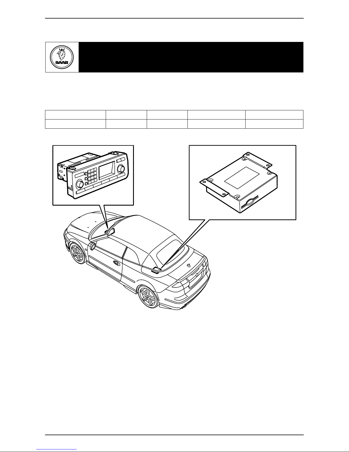
Saab 9-3 CV M04-
Integrated telephone
Accessories Part No. Group Date Instruction Part No. Replaces
12 832 505 9:39-13 Nov 03 12 832 515
F930A301
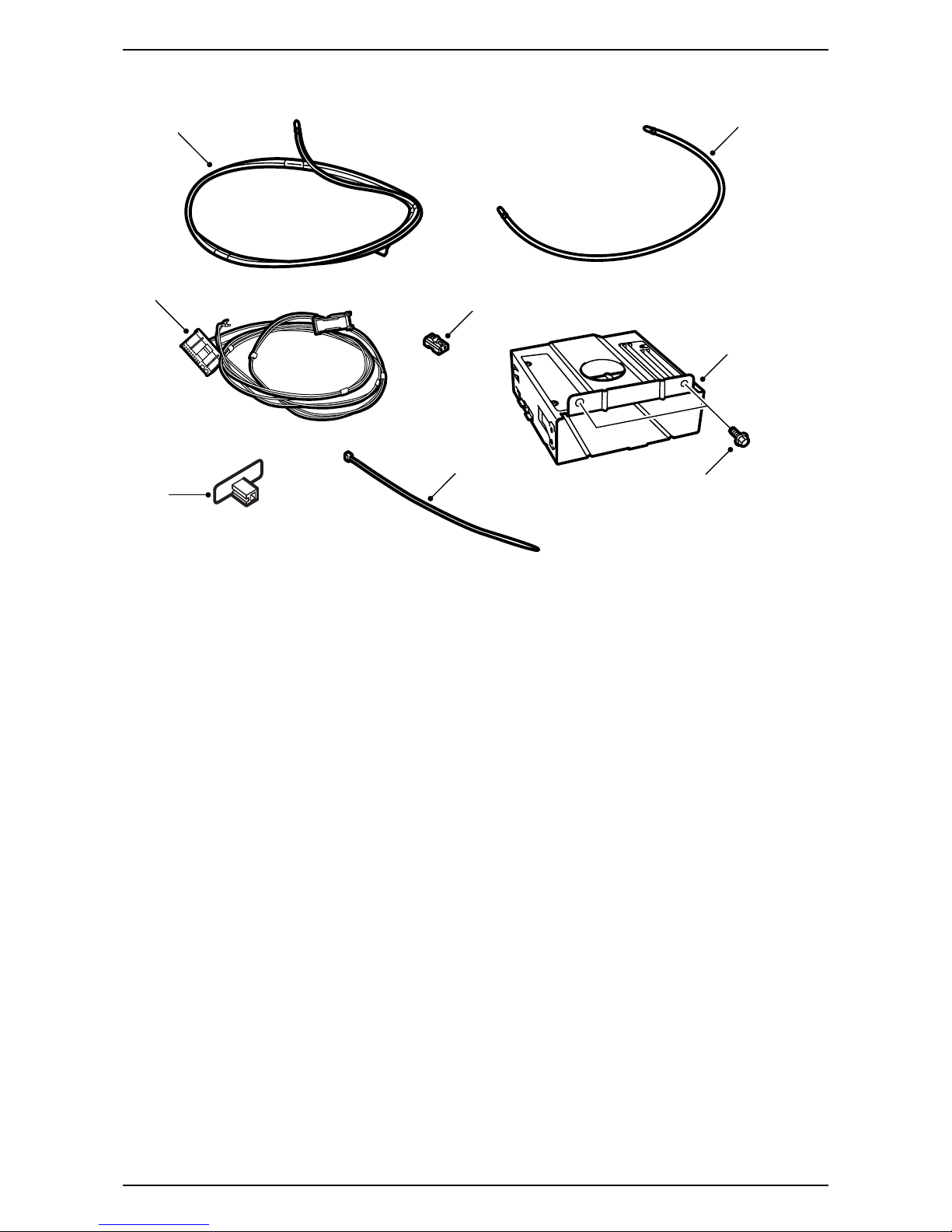
2 12 832 515
Saab 9-3 CV M04-
1 Fibre optic cable, A-pillar - Torsion compartment,
2770 mm long
2 Fibre optic cable (x3)
– Amplifier - Torsion compartment (870 mm long)
– Luggage compartment console - Torsion
compartment (1195 mm long)
– Between the units in the luggage compart-
ment console (455 mm long)
3 Wiring harness with fibre optic cable
4 Optical cable connector, 2-pin
5 Bracket for telematics unit
6 Screw (x2)
7 Antenna, Bluetooth
8 Cable tie (x17)
In addition, the following items are required
(ordered separately)
·Telematics unit
·Control panel (certain cars)
·Antenna cable (certain models)
·Steering wheel (certain cars)
F930A302
4
1
6
5
3
2
7
8
12 832 515 3
Saab 9-3 CV M04-
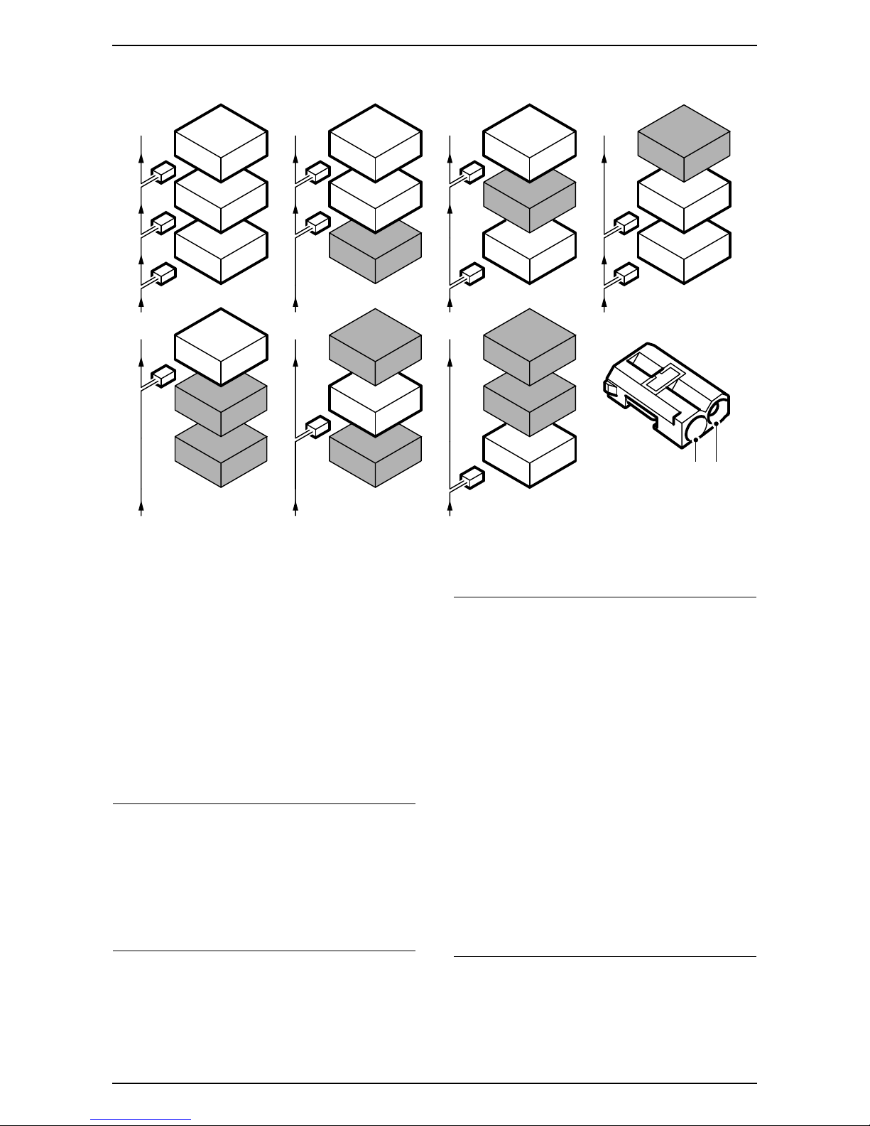
Bus Communication
Many parts of the car's electrical system communi-
cate using a bus. There are three types of bus
communication: P-bus (Powertrain Bus), I-bus
(Instrument Bus) and O-bus (Optical bus). The
audio system communicates via the O-bus together
with the navigation system, the telephone system
and others.
The O-bus is optical and is a ring bus. Two fibre
optical cables are connected to each control module
on the bus, one fibre optical cable for receiving and
one for sending. Messages received are converted
by each control module from a fibre optic signal to
electrical and then converted back to optical for
sending. The O-bus data transfer rate is 25 Mbit/s.
AMP1 is an amplifier behind the left-hand rear side
trim
AMP2 is an amplifier by the REC
CDC is a CD changer by the REC
DVD is a DVD player by the REC
When fitting new equipment to be connected to the
O-bus it is important that it is connected into the
correct side of the existing equipment.
Important
It is very important that everything connected to
the O-bus is connected in a specific order, see
illustration, and that the ring is closed the whole
time.
Connection in any other way than that described
in these fitting instructions may result in several of
the car's systems failing to work.
F930A100
1
2
CDC
1
2
DVD
1
2
AMP2
1
2
1
2
AMP2
CDC
1
2
1
2
AMP2
DVD
1
2
1
2DVD
CDC
1
2
1
2
1
2
AMP2
DVD
CDC
2 1
Important
Handle the fibre optic cables with care or the
signal may be distorted.
·It is very important that the two leads in the
connector are not confused with one another.
·Do not splice the cables.
·Do not bend the cable in a radius smaller than
25 mm.
·Do not expose the cable to temperatures
exceeding 85 °C.
·Keep the cable ends free from dirt and grime.
·Do not expose the cable to impact as this may
cause the transparent plastic to whiten,
thereby reducing the intensity of the light and
causing possible communication interruptions.
·The cable should not lie against any sharp
edges as this may cause increased signal
reduction.
4 12 832 515
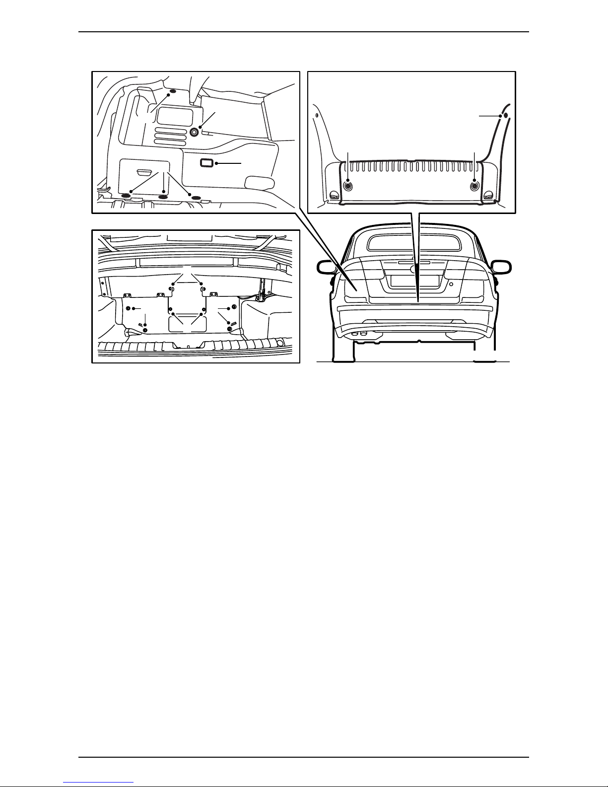
Saab 9-3 CV M04-
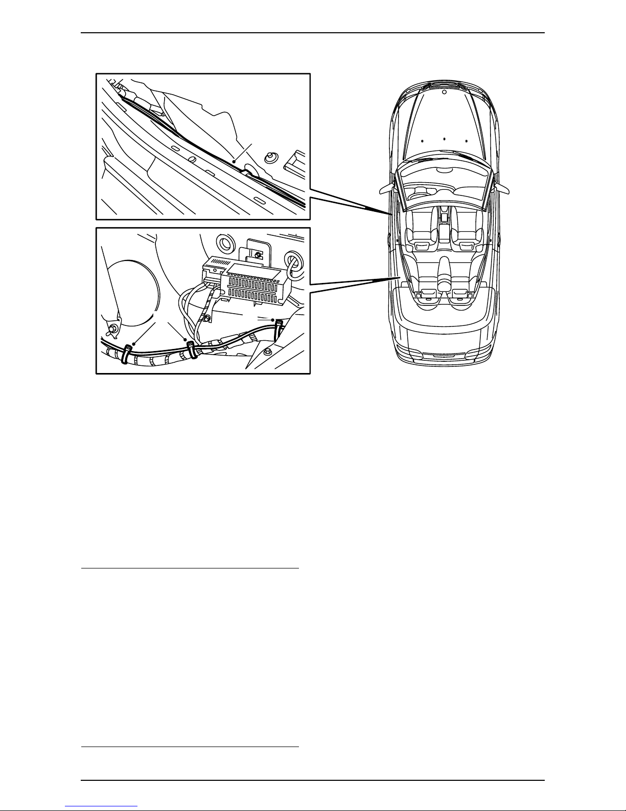
1 Raise the soft top and open the boot lid.
2 Remove the carpet on the luggage compartment
floor and remove the luggage compartment scuff
plate.
3 Remove the rivets and lift out the front section of
the luggage compartment trim.
4 Remove the side scuff plate on the left-hand
side.
5 Remove the clips for the left-hand side trim and
fold the trim aside. Unhook the strap on the rear
side of the side trim and remove the connector
from the luggage compartment lighting. Remove
the side trim.
6 Check from the luggage compartment if there is
a connection for the antenna cable in the centre
of the torsion compartment and if a telematics
unit is fitted in the centre of the torsion compart-
ment. If a telematics unit is fitted then it must be
removed together with the bracket but without
the connectors being removed.
No telematics unit and no antenna connec-
tion: Continue with step 7.
Telematics unit and blue antenna cable
connection fitted but no violet antenna cable
connection: Continue with step 7.
No telematics unit, and blue antenna cable
connection fitted, but no violet antenna
cable connection: Continue with step 7.
No telematics unit but violet antenna cable
connection fitted: Continue with step 22.
Telematics unit and blue antenna cable
connection fitted and connected, and violet
antenna cable connection is fitted but not
connected: Continue with step 61.
No telematics unit, but blue antenna cable
connection fitted and violet antenna cable
connection fitted: Continue with step 22.
F930A303
4
5
5
5
2 2
5
33
43
3
12 832 515 5
Saab 9-3 CV M04-
7 Fold down the soft top completely, but allow the
soft top cover to remain open.
8 Open the rear side window on the left-hand side
completely.
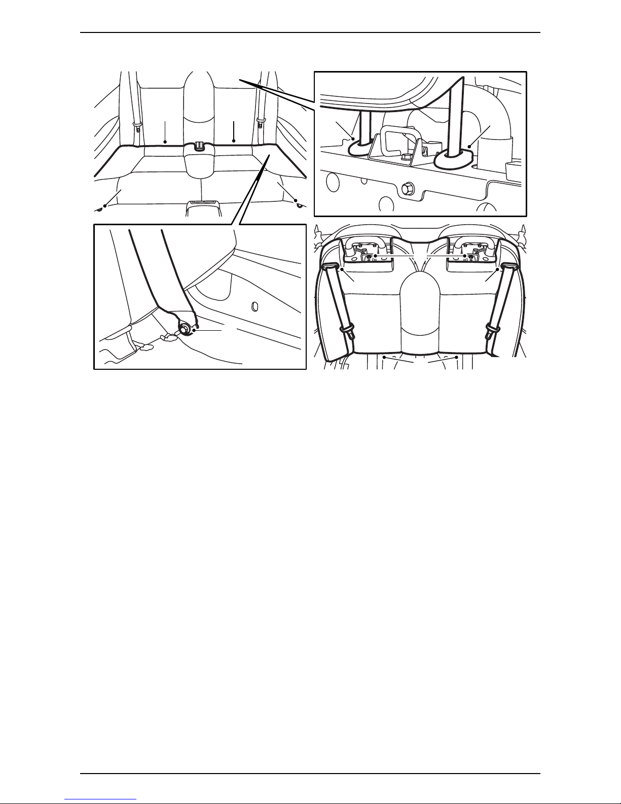
9 Remove the screws which hold the rear seat
cushion at the front edge.
10 Lift up the cushion and pull it forwards so that it
loosens.
11 Pull up both of the rear head restraints to the
highest position.
12 Press in the lock on the head restraints' sleeves.
Hold the lock pressed in and remove the head
restraints.
13 Remove the screws for the seat belts' lower
mounting.
14 Remove the two screws for the backrest cushion
upper mounting.
15 Pull the backrest cushion lower section forwards
and lift the backrest cushion upwards.
16 Press out the seat belt guide from the backrest
cushion and move the seat belt out from the
guide and the backrest cushion.
17 Lift out the backrest cushion.
F930A304
10 10 12 12
9
9
13
14
15
16 16
6 12 832 515
Saab 9-3 CV M04-
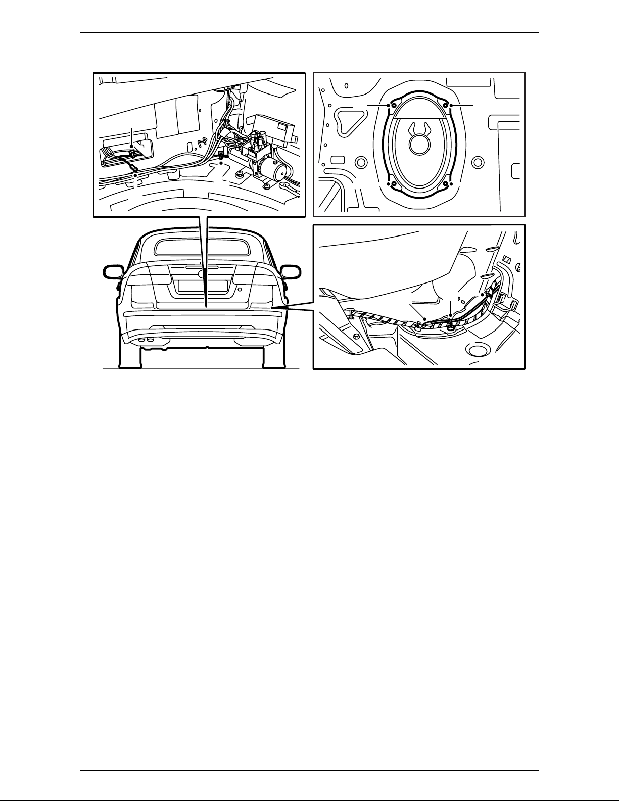
18 Locate the violet antenna cable connection at
the seat belt lower mounting on the right-hand
side of the car. Remove the connectors.
19 Remove the right-hand bass speaker or the
right-hand cover.
20 Cut off the cable tie in order to be able to change
the location of the antenna cable and fit a new
cable tie in the same place, but only around the
wiring harness.
21 Guide the antenna cable into the torsion
compartment and position the antenna cable
connection, together with the blue antenna
cable connection if fitted, at the centre of the
torsion compartment.
Without navigation: Continue with step 22.
With navigation: Continue with step 61.
F930A305
20
21 21
21 19
19
19
19
18
12 832 515 7
Saab 9-3 CV M04-
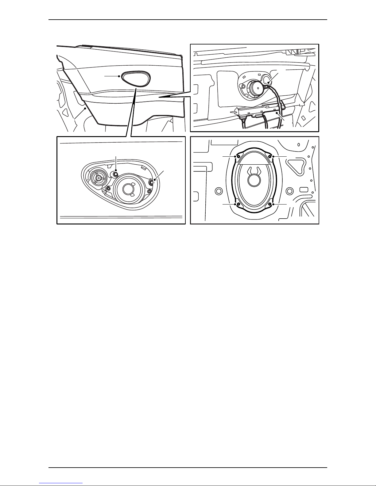
22 Carefully remove the speaker grille from the left-
hand rear side trim. Use removal tool 82 93 474.
23 Remove the screws which hold the rear side
trim on the left-hand side.
24 Lift the side trim upwards. Retain any rubber
protection.
25 Unhook the control module from the side trim,
but do not remove the control module connector
as this means a diagnostic trouble code being
generated.
26 Remove the speaker connector and remove the
side trim.
27 Remove the left-hand bass speaker or the left-
hand cover.
F930A306
22
23
23
24
26
25
27
27
27
27
8 12 832 515
Saab 9-3 CV M04-
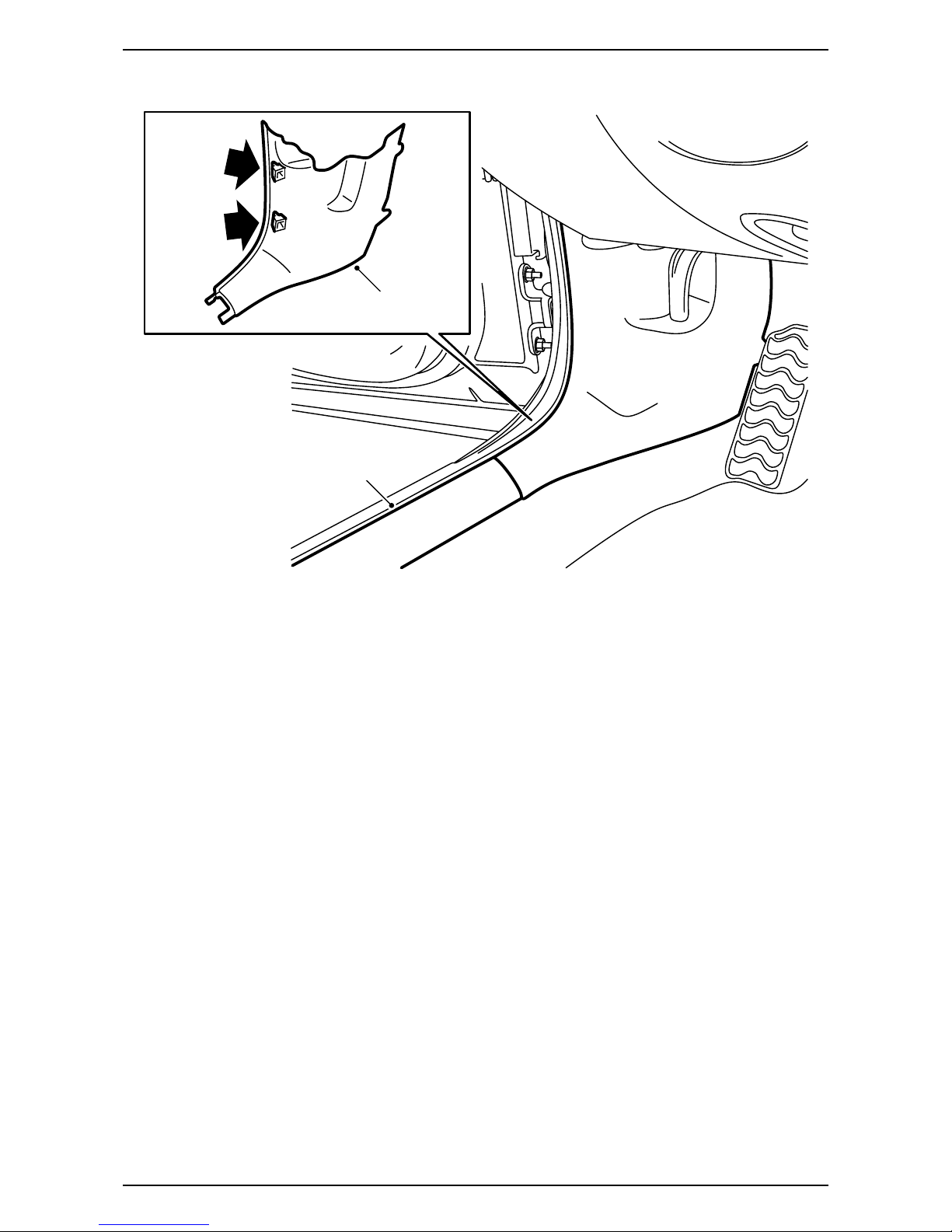
28 Remove the left-hand scuff plate.
29 Remove the lower section of the A-pillar trim on
the left-hand side.
F930A307
29
28
12 832 515 9
Saab 9-3 CV M04-
30 Position the left-hand front seat in its most
forward position and fold the backrest forwards.
31 Take the fibre optic cable, A-pillar - Torsion
compartment, from the kit and guide it from the
connector at the left-hand lower A-pillar via the
wiring harness by the scuff plate, under the rear
seat and to the left-hand roll-bar in the torsion
compartment. Secure the fibre optic cable with
cable ties.
32 Raise the soft top completely and open the boot
lid.
Note
The seat must be pushed to the rear position in
order to access the whole route. Following which,
push the seat back to the forward position.
Important
Handle the fibre optic cables with care or the
signal may be distorted.
·Do not bend the cable in a radius smaller than
25 mm.
·The cables must not be exposed to knocks
which cause the transparent plastic to whiten,
which means that the light intensity is weak-
ened. Such damage can cause an interruption
to communication.
·The cable should not lie against any sharp
edges as this may cause increased signal
reduction.
F930A308
31 31
31
10 12 832 515
Saab 9-3 CV M04-
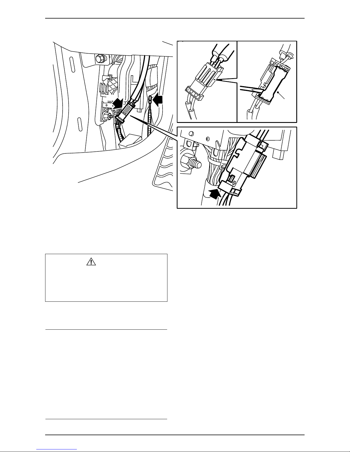
33 Remove the battery cover and the battery
negative cable.
34 Locate the connector with connected fibre optic
cables at the left-hand lower A-pillar (taped to
the cable duct) and lift up the connector lock tab.
35 Remove the fibre optic cable from the position in
the connector where the arrow points outwards,
to the fibre optic cable.
36 Remove the protective cover from the connection
to the kit's fibre optic cable and fit the protective
cover on the removed fibre optic cable's connec-
tion. Carefully move the fibre optic cable aside so
that it is not damaged and position it behind the
wiring harness.
37 Fit the connection on the fibre optic cable which
was fitted in step 31 in the connector and fit the
lock tab.
WARNING
The visible red light is a class 1 laser. Do not look
directly into the optical fibre or the control module
connector at close range. A distance of less than
20 mm between your eyes and the light source
may cause eye injury.
Important
Handle the fibre optic cables with care or the
signal may be distorted.
·It is very important that the two cables in the
connector are not mixed up.
·Do not bend the cable in a radius smaller than
25 mm.
·Keep the cable ends free from dirt and grime.
·The cable should not lie against any sharp
edges as this may cause increased signal
reduction.
F930A309
34
36
34
37
Table des matières
Autres manuels Saab Téléphone


