Rydeen BSS-ONE Manuel utilisateur

Owner’s Manual BSS-ONE
Single Sensor Blind Spot Detection System
V1.0


Contents
1
Contents
1. Welcome Statement & Warnings ............................................................ 2
PRECAUTIONS & WARNINGS ..............................................................................2
2. What’s in the Box
................................................................................... 4
3. Product Overview
................................................................................... 5
Wiring Diagram
..................................................................................................5
4. Installation
............................................................................................ 6
Installation Diagram
...........................................................................................7
5. Function Introduction
.......................................................................... 10
BLIND SPOT DETECTION (BSD)
........................................................................ 10
LANE CHANGE ALERT (LCA)
.............................................................................. 11
SYSTEM FUNCTION
....................................... ....................................................12
6. Specifications
....................................................................................... 12
7. Technical Support Contact Info
............................................................ 13
8. One Year Limited Warranty
.................................................................. 13
9. To Obtain Warranty Service
.................................................................. 14
10. FCC/ISED Compliance Statement
...................................................... . 14
11. Copyright
........................................................................................... 15
12. Disclaimer
.......................................................................................... 16
13. Troubleshooting
................................... .............................................. 16

Welcome Statement & Warnings
2
1. Welcome Statement & Warnings
PRECAUTIONS & WARNINGS
IMPORTANT INFORMATION
PLEASE READ THIS MANUAL CAREFULLY BEFORE
USING THE PRODUCT
The BSS-ONE
is designed to aid in detecting vehicles that may have entered the
vehicle blind spot zone, and will provide you with a safer, more comfortable and
convenient driving experience. Therefore, we recommend that you read and follow
all the information and instructions in this user manual to make your BSS-ONE
achieve the best performance and satisfaction.
Congratulations and thank you for purchasing RYDEEN BSS-ONE, Single Sensor Blind
Spot Detection System. We hope you will enjoy using this exciting product and trust
that it will make your driving experience more comfortable and hassle-free.
Please read this Owner’s Manual carefully. After you have finished reading the
instructions, keep this document in a safe place for future reference. If you have any
further questions about your BSS-ONE operation, feel free to call RYDEEN, Toll Free at
1-877-777-8811 (within USA only) for product support, or visit our website:
www.rydeenmobile.com
The BSS-ONE
IS NOT
TO
replace
any functions drivers shall ordinarily perform
in driving a motor vehicle, nor does it decrease the need for drivers to stay
vigilant and alert in all driving conditions, to obey all the safe driving standards,
practices, traffic rules and regulations. ALWAYS LOOK AHEAD, LOOK
AROUND, KEEP A SAFE DISTANCE FROM OTHER VEHICLES WHEN
DRIVING AND PARKING, DO NOT DEPEND SOLELY ON THE PRODUCT
FOR COMPLETE FIELD OF VIEW.
RYDEEN DOES NOT GUARANTEE 100% ACCURACY IN THE DETECTION OF
VEHICLES OR PEDESTRIANS, AND THEREFORE DOES NOT GUARANTEE
THE PERFORMANCE OF ANY RELATED AUDIO OR VISUAL WARNING
SIGNALS. FURTHERMORE, ROAD, WEATHER AND OTHER CONDITIONS
THE BSS-ONE ONLY WORKS ON VEHICLES WITH PLASTIC BUMPERS. IT
WILL NOT FUNCTION/WORK ON BUMPERS MADE OF METAL OR OTHER
COMPOSITE MATERIALS LIKE FIBERGLASS OR CARBON FIBER.

3
Welcome Statement & Warnings
WARNINGS
DO NOT DROP ANY COMPONENTS OF THIS PRODUCT. Excessive shock due
to dropping any components in the system or subjecting it to excessive shock
and vibrations may cause malfunction and is not covered by warranty.
Keep the BSS-ONE
unit
out
of
reach
of
small
children.
DO NOT disassemble or modify this product, as there are high-voltage
components inside that may cause an electric shock. Be sure to consult your
dealer or the nearest authorized
RYDEEN
service agent
for internal inspection,
adjustments or repairs.
This product cannot guarantee to avoid
all incidents.
THE FOLLOWING INSTRUCTIONS ARE RECOMMENDED FOR
AUTHORIZED RYDEEN MOBILE INSTALLERS.
and contact RYDEEN. Changes or modifications to the BSS-ONE will void the
warranty and its compliance with FCC rules.
If you notice any of the following: (Unidentified liquid on the unit; smoke rising
out of the unit; unusual odor emanating from the unit) – STOP USING THE
UNIT IMMEDIATELY. Contact the nearest RYDEEN retailer or call RYDEEN
Customer Service for assistance Toll Free @ 1-877-777-8811 (within USA only).
DO NOT mount your BSS-ONE on any non-automotive form of transportation
(motorcycles, bikes, ATV’s, watercraft).
The appearance of the product shown in this manual may be different from the
actual product, please refer to the actual product.
The picture examples used in this manual may be different compared to the
actual vehicle, please use as reference.
Position the unit (LED Indicators) in a location that does not obstruct the
driver’s view of the road, instruments or vehicle controls.
Make sure that the BSS-ONE device and the provided bracket or adhesive are
properly attached to the vehicle’s bumper.
DO NOT attempt to modify or disassemble the BSS-ONE unit. Personal injury or
damage could result. If a problem occurs, stop using the system immediately
MAY ADVERSELY AFFECT THE VEHICLE’S BLIND SPOT DETECTION
SYSTEM RECOGNITION AND RESPONSE CAPABILITIES.

4
2. What’s in the Box
When opening the packaging box of this product, please make sure that all product
accessories are complete.
What’s in the Box
Radar Sensor & Holder
Main Cable
Sensor Extension Cable
Left Indicator
Right Indicator
Buzzer
Splice Connector
K-520 Primer Adhesion Promoter Allen Key (large)
Allen Key (small)
Drill Bit (Φ14mm) &

Product Overview
5
3. Product Overview
Wiring Diagram

WARNINGS
Installation
4. Installation
THE FOLLOWING INSTRUCTIONS ARE INTENDED TO GIVE YOU A BRIEF
GUIDANCE FOR INSTALLATION. CAREFULLY READ THIS INSTALLATION
GUIDE AND ITS IMPORTANT SAFETY INSTRUCTIONS AND WARNINGS
PRIOR TO INSTALLING OR USING THE BSD SYSTEM.
For professional installation only by personnel with specialized training
and experience in mobile electronics.
Dropping your BSS-ONE
unit or subjecting it to excessive
shock and
vibrations as this may cause it to malfunction and is not covered by
warranty.
Do not install the LED Indicators where it may (i) obstruct the driver's
vision, (ii) impair the performance of any of the vehicle's operating
systems or safety features, including air bags or hazard lamp buttons or
(iii) impair the driver's ability to safely
operate the vehicle.
Never install this product in front of or next to the place in the dashboard,
door, or pillar from which one of your vehicle's airbags would deploy.
Please refer to the vehicle's owner's manual for reference to the
deployment area of the airbags.
Secure all wiring with cable clamps or electrical tape. Do not allow any
bare wiring to remain exposed.
Make sure that the cables and wires will not interfere with or become
caught in any of the vehicle's moving parts, especially brake, doors, or
any of the vehicle's controls.
If the wiring of this unit is located under a front seat, make sure it does
not obstruct seat movement. Route all leads and cords carefully around
the sliding mechanism so they do not get caught or pinched in the
mechanism and cause a short circuit.
Do not shorten any leads. If you do, the protection circuit (fuse holder,
fuse resistor or filter, etc.) may fail to work properly.
Use only the parts included with the unit to ensure proper installation.
The use of unauthorized parts can cause malfunctions.
Never feed power to other electronic products by cutting the insulation
of the power supply lead of this product and tapping into the lead. The
current capacity of the lead will be exceeded, causing overheating.
Use this unit with a 12-
Failure to do so may result in a fire or malfunction.
THE BSS-ONE ONLY WORKS ON VEHICLES WITH PLASTIC BUMPERS. IT
WILL NOT FUNCTION/WORK ON BUMPERS MADE OF METAL OR OTHER
COMPOSITE MATERIALS LIKE FIBERGLASS OR CARBON FIBER.
●
●
●
●
●
●
●
●
●
●
●
●
●
6
volt operated vehicle and negative grounding only.

Installation
7
Do not perform installation in rain or fog.
NOTE:
1. Ensure that the connector is inserted correctly according to the corresponding
label and the arrow marks of the wire connector at the connection point. When
connecting, ensure that the KEY or raised area of the connector mates with the
opposite connector. Do not force any connection
and ensure that the connector
mates properly.
2. To avoid any damage to the connectors, align the arrows on each of the
corresponding items, then firmly press connectors together to ensure a good
connection. Failure to properly install and connect the system components may
cause damage to the product and operation of the system.
3. The radar sensor should be kept in a position with low interference, otherwise it
may cause the detection to be insensitive or not work properly.
4. The radar sensor should be kept clean. The adhesion of ice, snow or mud will
affect the normal operation of the sensor.
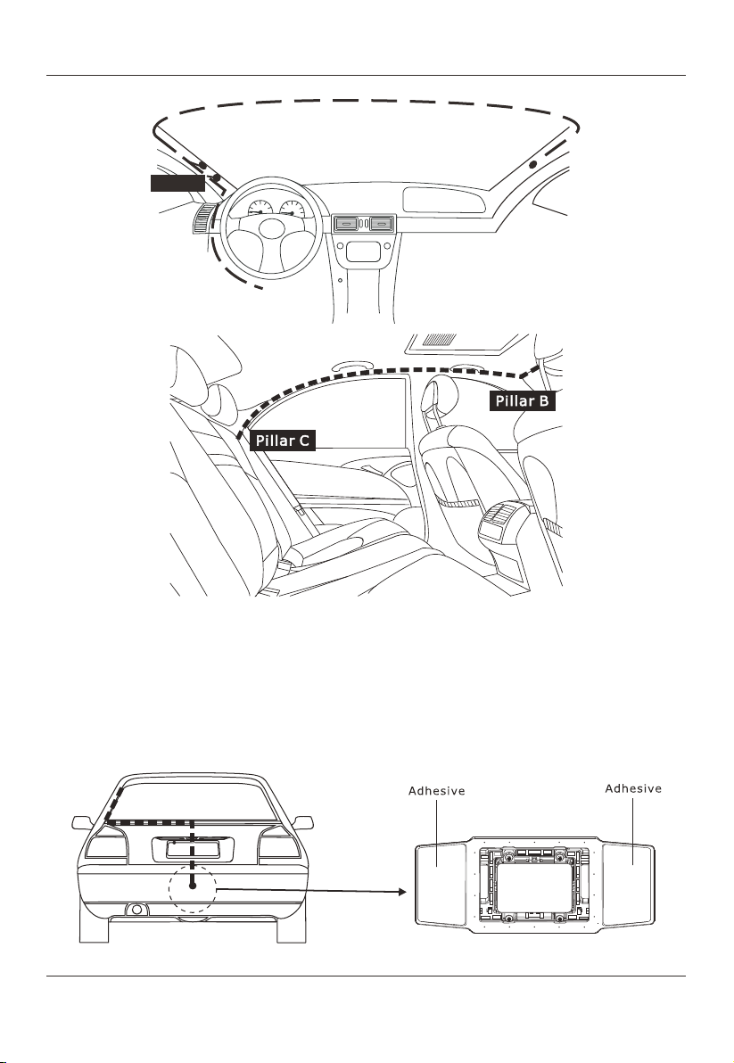
Installation Diagram
Secure the wiring with cable clamps or adhesive tape. Wrap adhesive
tape around wiring that comes into contact with metal parts to protect
the wiring.
●
●
Do not pull the connectors with excessive
force.
Do not pull the harness with excessive
force.
Fasten all connectors and terminals
securely.
Stress relieve harnesses and secure
properly.
Installation
8
Inside view
Step 1
Measure the rear bumper to locate a suitable mounting point, align the radar
sensor from the centerline of the vehicle, and along this axis, locate a position
parallel to the ground 15.5 inches to 31 inches from the ground so that the sensor
is mounted inside the bumper. Mark this spot on the outside of the bumper with
painter's tape.
Pillar A
ACC/IGN
GND
Indicator L Indicator R
Buzzer
Table des matières


