Royce Union Cruiser bicycles Manuel utilisateur

Owner’s Manual
for Cruiser Bicycles
Please read and fully understand this
manual before operation.
Save this manual for future reference.
This manual contains important safety,
assembly, operation and maintenance
information.
Basic Cruiser Owner’s Manual Royce Union v082712
Copyright Huffy Corporation 2012

2
Owner’s Manual Index
Your Bike
• Owner’s Bicycle Identification Record ................................3
• Fitting the Rider to the Bicycle............................................3
• Warning and Safety Information .........................................4
• Rules of the Road...............................................................4
• The Owner’s Responsibility................................................5
Assembly
• Parts Assembly View ..........................................................6
• Parts Assembly List.............................................................7
• Introduction.........................................................................8
• Tools Needed......................................................................8
• Front Fender Installation.....................................................9
• Assemble the Front Wheel to the Fork ..............................10
• Rear Fender Assembly ......................................................11
• Handlebar and Stem Installation........................................12
• Testing Stem and Handlebar Tightness.............................13
• Seat Installation .................................................................14
• Testing Seat Clamp and Post Clamp Tightness.................15
• Front Reflector Bracket Installation....................................16
• Rear Reflector Bracket Installation ....................................16
• Pedal Installation................................................................17
Maintenance and Service
• Brake System.....................................................................18
• Chain Adjustment...............................................................18
• Tires...................................................................................19
• Repair and Service ............................................................20
• Lubrication .........................................................................20
• Lubrication Table................................................................20
• Inspection of the Bearings .................................................21
• Reflectors...........................................................................21
Royce Union Warranty
• Royce Union Limited Warranty..........................................22
3
Owner’s Bicycle Identification Record
NOTE: This information is only available on the bicycle itself. It is not available
from Royce Union.
Each Royce Union bicycle has a Se-
rial Number stamped into the frame.
The Serial Number (1) can be found
on the bottom of the crank housing
as shown.
x
x
x
x
x
x
x
x
1
Write this number below to keep it for future reference.
If the bicycle is stolen, give this number and a description of the bicycle to the
police. This will help them find the bicycle.
Model / Serial Number:
Purchase Date:
Model Name:
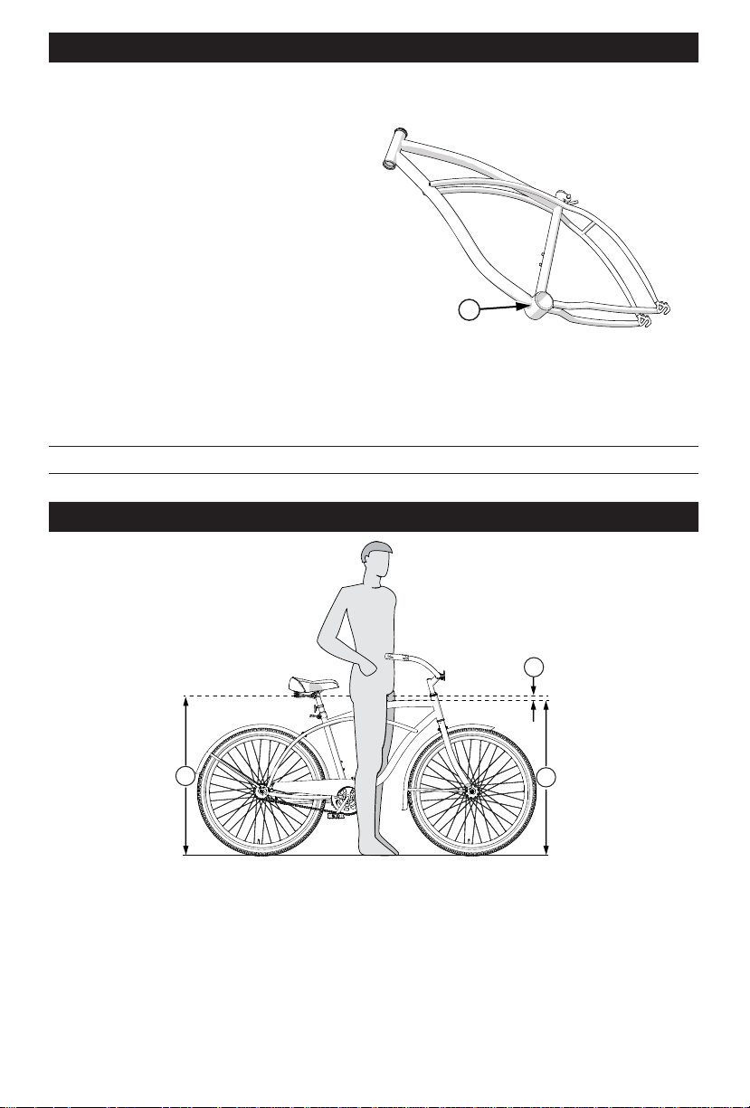
Fitting the Rider to the Bicycle
3
1
2
To determine the correct size of bicycle for the rider:
• Straddle the assembled bicycle with feet shoulder width apart and flat on
the ground.
• There must be at least 1 inch (2.5 cm) of clearance (1) between the high-
est part of the top tube (2) and the crotch of the rider with tires properly
inflated.
• The minimum leg-length for the rider is the highest part of the top tube plus
one inch (3).

4
Rules of the Road
WARNING: Failure of the rider to obey the following “Rules of the Road”
can result in injury to the rider or to others.
• Obey all traffic regulations, signs, and signals.
• Always wear a bicycle helmet that meets CPSC safety standards, as well
as local safety standards.
• Ride on the correct side of the road, in a single file, and in a straight line.
• If possible, avoid riding at night, dusk, dawn and any other time of poor
visibility.
• If you must ride at night or at time of poor visibility:
• Purchase, install, and use a headlight and taillight.
• Headlights are required by all states for nighttime riding and taillights
are required in some states.
• Battery-powered lights or flashing safety lights are also recommended.
• Make sure the reflectors of your bicycle are correctly positioned. Do not
remove the reflector or replace the reflectors with lighted devices that
look similar to reflectors.
• Make yourself more visible to motorists.
• Wear light-colored or reflective clothing, such as a reflective vest and
reflective bands for your arms and legs.
• Use reflective tape on your helmet.
Warning and Safety Information
Meanings of Warnings:
aThis symbol is important. See the word “CAUTION” or “WARNING”
which follows it.
The word “CAUTION” is before mechanical instructions. If you do not obey
these instructions, mechanical damage or failure of a part of the bicycle can
occur.
The word “WARNING” is before personal safety instructions. If you do not
obey these instructions, injury to the rider or to others can occur.
• Do not add a motor to the product.
• Do not tow or push the product.
• Do not modify the product.
• Replace worn or broken parts immediately.
• If anything does not operate properly, discontinue use.

5
• Do not let anything cover the reflectors.
• Use extra caution in wet weather:
• Ride slowly on damp surfaces because the tires will slide more easily.
• Avoid these hazards to prevent loss of control or damage to your
wheels:
• Be aware of drain grates, soft road edges, gravel or sand, pot holes or
ruts, wet leaves, or uneven paving.
• Cross railroad tracks at a right angle to prevent the loss of control.
• Avoid unsafe actions while riding.
• Do not carry any passengers.
• Do not carry any items or attach anything to your bicycle that could
hinder your vision, hearing, or control.
• Do not ride with both hands off the handlebar.
The Owner’s Responsibility
WARNING: This bicycle is made to be ridden by one rider at a time for
general transportation and recreational use. It is not made to withstand the
abuse of stunting and jumping.
If the bicycle was purchased unassembled, it is the owner’s responsibility to fol-
low all assembly and adjustment instructions exactly as written in this manual,
and any “Special Instructions” supplied and to make sure all fasteners and
components are securely tightened.
NOTE: Periodically check that all fasteners and components are securely
tightened.
If the bicycle was purchased assembled, it is the owner’s responsibility, before
riding the bicycle for the first time, to make sure the bicycle has been assem-
bled and adjusted exactly as written in this manual, and any “Special Instruc-
tions” supplied and to make sure all fasteners and components are securely
tightened. NOTE:
If product is assembled, please proceed to pages 13 and 15: Testing
Stem, Handlebar and Seat Clamp tightness.
6
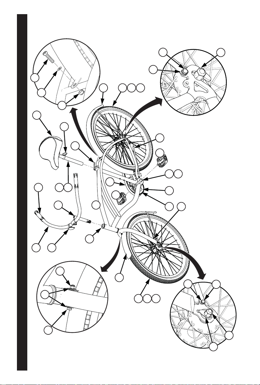
Parts Assembly View
14
10
15
11
9
10
31
21
25
27
26
30
1
20
19 28
6
4
5
7
16
29
6
7
5
18
24
34
13
33
17
12
3
32
2
22
23
22
23
9
8

7
Parts Assembly List
No. Description No. Description
1 Frame 19 Left Pedal
2 Front Wheel Assembly 20 Right Pedal
3 Front Fender 21 Fork
4 Wheel Retainer (x2) 22 Tire (x2)
5 Axle Nut (x4) 23 Tube (x2)
6 Washer (x4) 24 Grips (x2)
7 Fender Brace Bolt (x4) 25 Crank
8 Front Fender Mount Bolt 26 Crank Bearings
9 Washer (x3) 27 Sprocket
10 Nut (x2) 28 Kickstand
11 Rear Fender Mount Bolt 29 Rear Wheel Assembly
12 Handlebar 30 Chain
13 Handlebar Stem 31 Chainguard
14 Seat 32 Head Set Bearing
15 Quick Release Lever & Nut 33 Seat Post
16 Rear Fender 34 Seat Post Hardware
17 Front Reflector
18 Rear Reflector

8
Tools Needed
Small Adjustable Wrench
(Jaws must open at least 9/16 inch.) Open-end Wrenches
Flat-blade Screwdriver Phillips Screwdriver
Slip-Joint Pliers Metric Allen Wrenches
Introduction
This Owner’s Manual is made for several different bicycles. Some of the il-
lustrations may not look exactly like the parts of the bicycle, but the instructions
are correct. If the bicycle has any parts that are not described in this manual,
look for separate “Special Instructions” that are supplied with the bicycle.
Do not dispose of the carton and packaging until you complete the assembly of
the bicycle. This can prevent accidentally discarding parts of the bicycle.
WARNING: Keep small parts away from children during assembly.
NOTE: All of the directions (right, left, front, rear, etc.) in this manual are as
seen by the rider while seated on the bicycle.
All features, components and accessories are not included on all models.
9
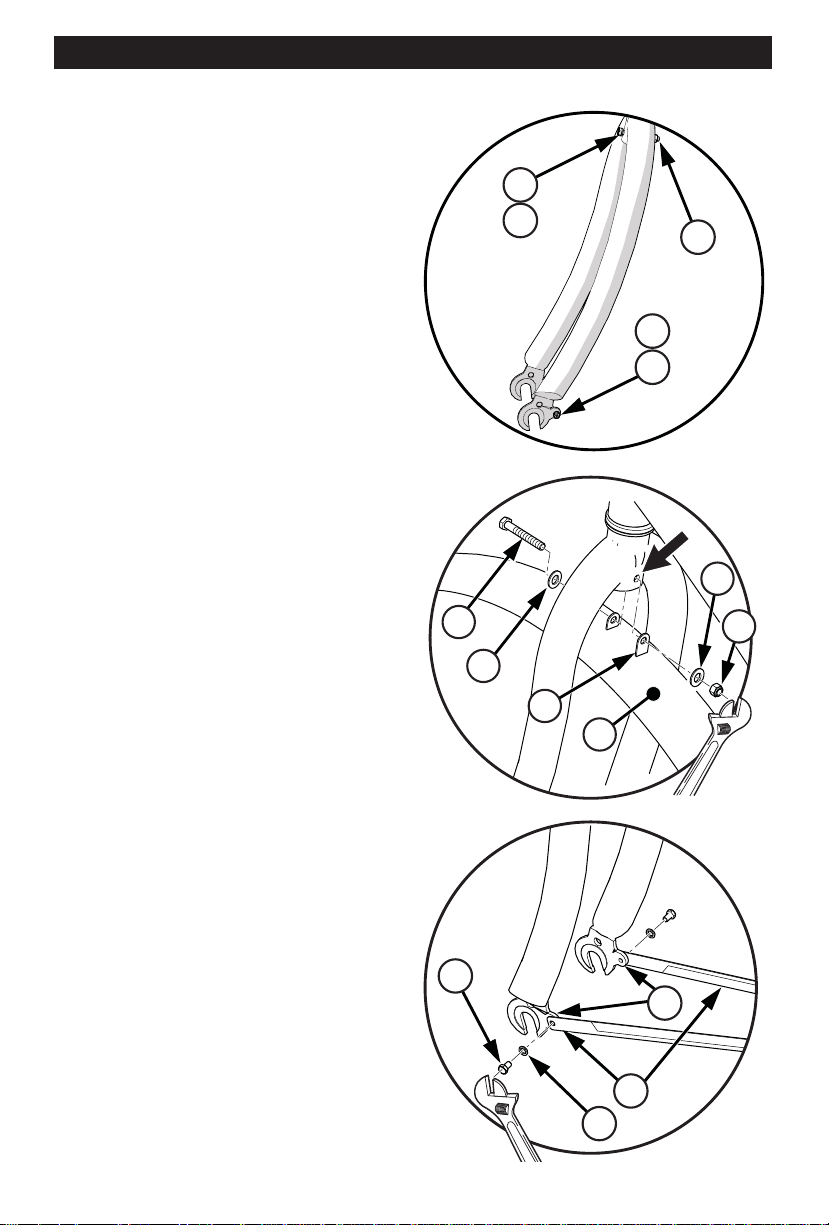
Front Fender Installation
Use Screw Driver and Wrench:
1. Front fender attaching hardware
has been pre-assembled onto the
fork. Remove the Bolt (8) and
Washer (9) and Nut (10) from the
fork crown.
2. Remove lower mounting Bolts (7)
and Washers (6) from the dropout
before starting (fig 01).
g 01
7
6
8
910
3. Place the Fender (3) in the fork
with the longer fork mounting tab
(A) on the rear side of the fork (fig
02).
4. Insert the Bolt (8) through the
Washer (9) and Fender tabs and
fork mounting hole.
5. Install Washer (9) and Nut (10)
onto Bolt (8) and tighten securely.
g 01
g 02
8
9
A
10
9
3
6. Line up the lower Fender Braces
(B) with the Fork Mounting Tabs
(C) (fig 03).
7. Insert each lower mounting Bolt
(7) and Washer (6) into the Fork
Mounting Tabs (C) and tighten
securely.
g 03
7
6
B
C
10
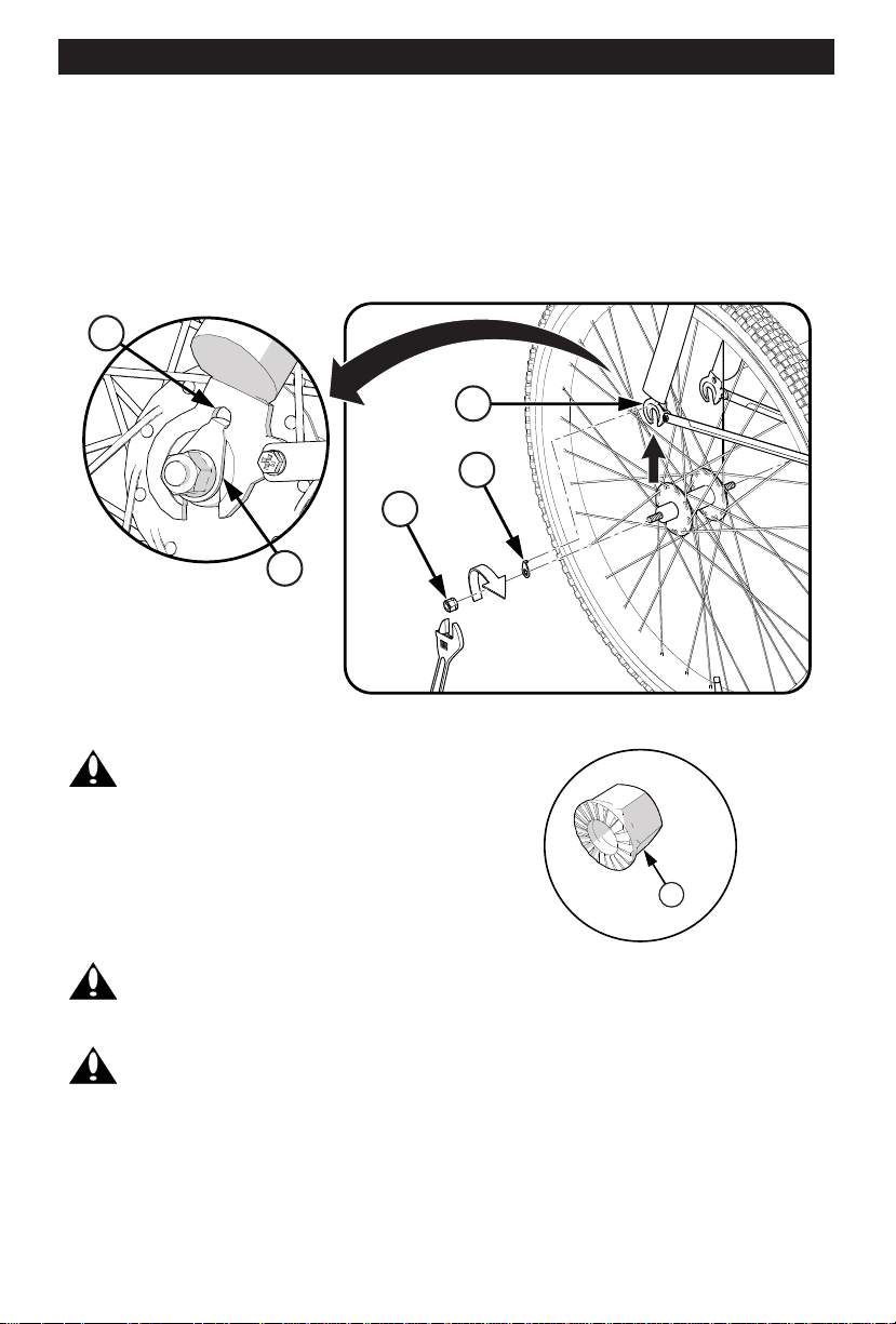
Assemble the Front Wheel to the Fork
1. If the Axle Nuts (5) are already attached to the front wheel axle, begin by
removing them with an open end wrench or adjustable wrench.
2. Set the wheel into the front fork (21) (fig 04).
3. Install wheel retainers (4) making sure the tabs are in the fork (D) tab
holes.
4. Attach the front wheel with the Axle Nuts (5).
5. Tighten Axle Nuts to 21 ft-lbs.
g 04
21
4
4
5
D
Note: Ensure wheel spins freely without contacting fork or fender.
WARNING: Do not use Nuts (5)
without serrations to attach the front
wheel.
5
WARNING: Put the wheel in the center of the fork and tighten
both nuts to the recommended torque of 21 ft.-lbs.
WARNING: Failure to obey these steps can allow the front wheel to
loosen while riding. This can cause injury to the rider or to others.
Table des matières


