RooDog Avatar Manuel utilisateur

RooDog Electric Bicycle
USER
MANUAL
EN 15194 official standard.
Black
Pantone Red 032C
Pantone Blue 072C
Avatar & Avatar ST

2 |www.roodog.co.uk

www.roodog.co.uk |3
Identity:
Frame number:
Date purchased:
Dealer stamp:

4 |www.roodog.co.uk
Thank you for buying a RooDog electric bike. This is one of the best purchases
you will ever make providing it is cared for properly.
Important: Please read this manual carefully before use and follow
instructions provided at all times
For your own safety check brakes, gears, lights and tyre pressures are fully
operational and correct before any bike ride. Also check all fasteners,, quick
release bolts and anything else that may be of hazard prior to setting off.
Important:
Please read & follow battery care guide lines in this booklet before first use.

www.roodog.co.uk |5
Contents
1 x Electric bike, 1 x Battery, 1 x Charger and 1 x User Manual
Index
Parts I.D ......................................................................................................................................................6
Battery Charging and removal....................................................................................................7
Bike assembly...................................................................................................................................... 10
How to use power assistance................................................................................................... 11
King Meter display ........................................................................................................................... 12
Maintenance ....................................................................................................................................... 16
Troubleshooting................................................................................................................................ 18
Warranty................................................................................................................................................. 20
Specifications...................................................................................................................................... 21

6 |www.roodog.co.uk
Parts I.D
We continually strive to give the best products
possible to our customers and therefore parts
are subject to change without notice.
1
12
5
2
64
15
17 16
7
8
9
11
3
10
13
14
1. Saddle
2. Lights
3. Front suspension
4. Front disc brake
5. Rear disc brake
6. Front chain ring
7. Rear 7 speed gears
8. Gear selector
9. LED Display
10. Key Ignition switch
11. Front & rear mudguards
12. Battery cover
13. Battery charge point
14. Bike Frame
15. Pedals
16. Side stand
17. Rear wheel hub motor

www.roodog.co.uk |7
Battery Charging & Removal
Step 1.
Put the silver key in and turn 90 degrees to the right and hold in
that position. Lift up bottom part of the cover until it releases.
Step 3.
Once the cover is removed, undo the Velcro strap then lift up the
top half of the battery about halfway (enough so you can grab
hold of it) Then slide the battery up towards the handlebars. It
should release from the connection point allowing you to then
lift the battery out.
Step 2.
Place hand at the top of the cover & whilst lifting the bottom up
in the air, slide THE COVER down towards the floor. TIP: LUBRICATE
AROUND TOP HALF OF COVER AND BIKE FRAME TO MAKE RELEASE EASIER.
Step 4.
At the bottom of the battery is a connection lead that connects
the battery to the charge point on the side of the bike. If this
is CONNECTED you will have to remove it prior to lift out the
battery. (this is also where you charge the battery when battery
is removed)

8 |www.roodog.co.uk
Battery Charging & Removal Continued
Replacement
Step 1.
Replace the connection lead for the charge point on the side of the bike (see step 4 on previous page) then
place the bottom half of the battery in first, making sure the connection prongs line up correctly. Slide it
down so the prongs fit inside of the battery then drop the top of the battery in. Don’t worry if it doesn’t sit
level at first just simple press the bottom of the battery down until it does. Then re-strap the Velcro together
to hold the battery in position.

www.roodog.co.uk |9
Step 2
Replace the connection lead for the charge point on the
side of the bike (see step 4 on previous page) then place the
bottom half of the battery in first, making sure the connection
prongs line up correctly. Slide it down so the prongs fit inside
of the battery then drop the top of the battery in. Don’t worry
if it doesn’t sit level at first just simple press the bottom of the
battery down until it does. Then re-strap the Velcro together to
hold the battery in position.
Step 3
Place hand at the bottom of the cover and press firmly down
until you here the lock click.
Battery Charging & Removal Continued
Replacement

10 |www.roodog.co.uk
Bike Assembly:
Tools Required: 4 and 5 mm Allen keys, 10 and 15 mm spanners
›Remove all packaging carefully: and select a good area to
assemble the bike. Preferably on a non abrasive surface so you
don’t damage the bike.
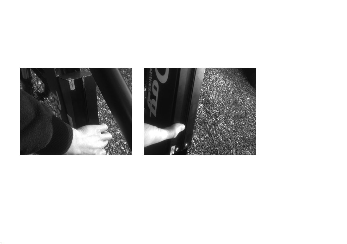
›Easier with two people: Have someone hold the bike
upright for you. Then remove the bolt on the arch of the
front suspension fork using the 10mm spanner and the 5
mm Allen key.
›Front Light: Assemble the front light (you will find this in your
accessories pack) Place the front light bracket over the bolt hole
and replace the bolt fully but do not put the nut back on. Then
fit the two small wires to the light assembly by simply pushing
them on to the metal spades.
›Front mudguard: On the back of the fork arch hang the loop of
the front mudguard over the bolt and then replace the 10mm
nut and tighten with the spanner and Allen key.
›Handle bars: Remove all the 4/5mm handle bar bolts and
bracket at the end of the stem, place handle bars in position
then replace the bracket and bolts, tightening with fingers
first. Once all 4 bolts are situated correctly you can tighten with
the 4/5mm Allen key but do this from corner to corner and
only a little bit at a time on each to keep the bracket even. For
example: tighten top right corner bolt first, then bottom left
corner bolt second and so on.
›Front wheel: Place bike in a bike maintenance stand or turn up
side down so the bike is standing on the handlebars and saddle
but again try to do this on a non abrasive surface to avoid
damage. (remove battery first in order to lighten and make it
easier to maneuver the bike) Once in position take the front
wheel and the quick release skewer/axle bolt. Undo the plastic
end cap and take off one spring (leaving one spring on). Slide
the bolt through the Centre of the front wheel until it comes
out the other side, then place the spring back on first (small end
first) followed by the plastic end cap and loosely tighten. Prior to
inserting wheel make sure the tyre will be spinning in the right
direction (see tyre sidewall). Pick the wheel up and slide into the
slots provided on the front fork and push downwards until it
stops. Once aligned you can tighten up the skewer bolt. (lever
should point upward when fitted correctly)
›Disc brake: If not already correct adjust brake by releasing
brake cable with 5mm Allen key then adjust accordingly and re-
tighten. Spin the wheel to make sure it spin freely. You can make
minor adjustments by turning the plastic screw located on the
brake cable near the brake caliper.
Note: Your wheel should fully stop once the brake lever
is depressed halfway. If it does not stop, re-adjust them
accordingly.
Ce manuel convient aux modèles suivants
1
Table des matières
Autres manuels RooDog Vélo

RooDog
RooDog Chic Manuel utilisateur

RooDog
RooDog Bliss Manuel utilisateur

RooDog
RooDog Tourer Manuel utilisateur

RooDog
RooDog Cosmo Manuel utilisateur
RooDog
RooDog Avatar 2.0 Manuel utilisateur

RooDog
RooDog Tourer Manuel utilisateur

RooDog
RooDog Rogue Manuel utilisateur

RooDog
RooDog Mayfair Manuel utilisateur

RooDog
RooDog Polka dot Manuel utilisateur


