Rockford Fosgate FNX2414 Mode d’emploi

FNX2414
FNX2514
FNX2614U
FNX2614
Installation
& Operation
Páginas de Referencia para la Instalación
Schéma d’Installation
Installations Beiblatt
Istruzioni di Installation
COMPONENT SYSTEM

– i –
Dear Customer,
Congratulations on your purchase of the world's finest brand of car audio speakers.
At Rockford Fosgate, we are fanatics about musical reproduction at its best, and we
are pleased you chose our product. Through years of engineering expertise, hand
craftsmanship, and critical testing procedures, we have created a wide range of
products that reproduce music with all the clarity and richness you deserve.
For maximum performance, we recommend you have your new Rockford Fosgate
product installed by an Authorized Rockford Fosgate Dealer, as we provide special-
ized training through Rockford Technical Training Institute (RTTI). Please read your
warranty and retain your receipt and original carton for possible future use.
Great product and competent installations are only a piece of the puzzle when it
comes to your system. Make sure that your installer is using 100% authentic instal-
lation accessories from Connecting Punch in your installation. Connecting Punch
has everything from RCA cables and speaker wire to Power line and battery con-
nectors. Insist on it! After all, your new system deserves nothing but the best.
To add the finishing touch to your new Rockford Fosgate image, order your Rockford
wearables, which include everything from T-shirts and jackets to hats and sunglasses.
To get a free brochure on Rockford Fosgate products and Rockford accessories, in
the U.S. call 480-967-3565 or FAX 480-967-8132. For all other countries, call +001-
480-967-3565 or FAX +001-480-967-8132.
PRACTICE SAFE SOUND™
CONTINUOUS EXPOSURE TO SOUND PRESSURE LEVELS OVER
100dB MAY CAUSE PERMANENT HEARING LOSS. HIGH POWERED
AUTOSOUND SYSTEMS MAY PRODUCE SOUND PRESSURE LEVELS
WELL OVER 130dB. USE COMMON SENSE AND PRACTICE SAFE
SOUND.
If, after reading your manual, you still have questions regarding this product, we rec-
ommend that you see your Rockford Fosgate dealer. If you need further assistance,
you can call us direct at 1-800-669-9899. Be sure to have your serial number, model
number, and date of purchase available when you call.
The serial number can be found on the outside of the box. Please record it in the space
provided below as your permanent record. This will serve as verification of your facto-
ry warranty and may become useful in recovering your product if it is ever stolen.
Serial Number: __________________________________
Model Number:__________________________________

– ii –
Introduction ..............................................................................................1
Package Contents......................................................................................1
Installation Considerations........................................................................2
Mounting Location....................................................................................3
Installation ................................................................................................4
Troubleshooting ........................................................................................8
Specifications............................................................................................9
Warranty Information ..............................................................................11
International Information ........................................................................12
GETTING STARTED
Welcome to Rockford Fosgate! This manual is designed to provide information
for the owner, salesperson, and installer. For those of you who want quick
information on how to install this product, please turn to the
Installation
Section
of this manual or refer to the icons listed below. Other information can
be located by using the Table of Contents. We, at Rockford Fosgate, have
worked very hard to make sure all the information in this manual is current.
But, as we are constantly finding new ways to improve our product, this infor-
mation is subject to change without notice.
TABLE OF CONTENTS
Sections marked
TROUBLESHOOTING
include recommendations for
curing installation problems
Sections marked
INSTALLATION
include “slam dunk”
wiring connections
I
N
S
T
A
L
L
A
T
I
O
N
+ -
+ -
TROUBLE-S
H
O
O
T
I
N
G
Visit our website for the latest information on all Rockford products.

–1 –
(2) FNX2401 Tweeters —Includes 3/4"
[20mm] silk dome tweeter, flush mount
housing, surface mount housing, wedge
mount housing
(2) Tweeter Mounting Brackets
(4) #8-32 x .500 Screws
(8) #8 x .75 Phillips Screws
(2) .110 Female Fast-on Connectors
(2) .110 Male Fast-on Connectors
(2) FNX1404 4" Midrange Speakers
(2) 4" Speaker Grilles
(2) 4" Speaker Grille Rings
(2) FNX242x 2-Way Crossovers
(8) #8 x 1.25 Phillips Screws
(20') 18-Gauge Speaker Wire
(2) FNX2401 Tweeters —Includes 3/4"
[20mm] silk dome tweeter, flush mount
housing, surface mount housing, wedge
mount housing
(2) Tweeter Mounting Brackets
(4) #8-32 x .500 Screws
(8) #8 x .75 Phillips Screws
(2) .110 Female Fast-on Connectors
(2) .110 Male Fast-on Connectors
(2) FNX2406U 6" Midrange Speakers
(2) 6" Speaker Grilles
(2) 6" Speaker Grille Rings
(2) FNX242x 2-Way Crossovers
(8) #8 x 1.25 Phillips Screws
(20') 18-Gauge Speaker Wire
(2) FNX2401 Tweeters —Includes 3/4"
[20mm] silk dome tweeter, flush mount
housing, surface mount housing, wedge
mount housing
(2) Tweeter Mounting Brackets
(4) #8-32 x .500 Screws
(8) #8 x .75 Phillips Screws
(2) .110 Female Fast-on Connectors
(2) .110 Male Fast-on Connectors
(2) FNX2405 5-1⁄4" Midrange Speakers
(2) 5-1⁄4" Speaker Grilles
(2) 5-1⁄4" Speaker Grille Rings
(2) FNX242x 2-Way Crossovers
(8) #8 x 1.25 Phillips Screws
(20') 18-Gauge Speaker Wire
FNX2414 4" fanaticX Component System
FNX2614U 6" fanaticX Component System
FNX2514 5-1/4" fanaticX Component System
(2) FNX2401 Tweeters —Includes 3/4"
[20mm] silk dome tweeter, flush mount
housing, surface mount housing, wedge
mount housing
(2) Tweeter Mounting Brackets
(4) #8-32 x .500 Screws
(8) #8 x .75 Phillips Screws
(2) .110 Female Fast-on Connectors
(2) .110 Male Fast-on Connectors
(2) FNX2406 6-1⁄2" Midrange Speakers
(2) 6-1⁄2" Speaker Grilles
(2) 6-1⁄2" Speaker Grille Rings
(2) FNX242x 2-Way Crossovers
(8) #8 x 1.25 Phillips Screws
(20') 18-Gauge Speaker Wire
FNX2614 6-1/2" fanaticX Component System
This manual provides information on the features and installation of the
fanaticX Systems. We suggest you save this manual for future reference. We
strongly recommend you have your Authorized Rockford Fosgate Dealer
install the fanaticX System. If you do choose to install the system yourself,
please be sure to read the entire manual before beginning.
INTRODUCTION
PACKAGE CONTENTS

–2 –
Tools Needed
The following is a list of some of the tools necessary for the installation of your
speakers.
•Power Drill with assorted bits •#2 Phillips Screwdriver
•Tape Measure •Voltmeter
General
1. For safety, disconnect the negative lead from the battery prior to beginning
the installation.
2. Never run wires underneath the vehicle. Running the wires inside the vehi-
cle provides the best protection.
3. Avoid running wires over or through sharp edges. Use rubber or plastic
grommets to protect any wires routed through metal.
4. Mount the speakers/crossovers away from electrical sources (other than the
amplifier) i.e., power cables, electronic fuel pumps, vehicle computers,
and other potential noise sources.
5. Mount the speakers/crossovers away from areas of extreme heat or mois-
ture.
Speakers
1. Make sure there is an area large enough of the speaker to mount. Warning!
Failure to do this can cause damage to the speaker if the speaker frame is
bent during installation.
2. Check to see that the location is deep enough for the speaker(s) and the
location does not interfere with the normal operation of the vehicle.
3. When mounting the speaker(s) in the door of a vehicle, make sure the
speaker(s) do not interfere with either the door or window operation.
4. When mounting the speaker(s) on the rear deck of the vehicle, check the
operation of the rear hatch or trunk lid. Make sure the torsion bars and
other moving parts are not obstructed by the speaker(s) installation.
•Please refer to the Specifications section of this manual for proper mount-
ing diameter and depth of the speaker(s).
Crossovers
1. Make sure there is a flat area large enough for the crossover to mount.
2. For best results, mount the crossover(s) next to the amplifier for a decora-
tive finish to the installation and provide an easy upgrade (no new wires to
run) for a bi-amp Rockford Fosgate system in the future.
INSTALLATION CONSIDERATIONS
I
N
S
T
A
L
L
A
T
I
O
N
+ -
+ -
–3 –
•Sound radiated from a “point source”provides the best stereo imaging
because the separation of the acoustical centers between the midrange
and tweeter for each channel is at the optimum distance. In a closed en-
vironment such as an automobile, horizontal speaker alignment (Figure
2-A) can cause severe amplitude and phase differences which will
degrade not only the imaging, but also the frequency response. This is
due to the path length differences between the midrange and tweeter.
With a vertical alignment (Figure 2-B), the path length difference
A solid front stage with a good image is one of the most difficult tasks to
achieve in a vehicle. No car has the optimum listening environment. This
makes proper sound staging very difficult to accomplish. Most speakers
tend to be placed where they will fit easily, as opposed to where they can
perform the best. The mounting location of your speakers will have a great
effect on the sound quality of your stereo system. The special care taken to
place the speakers will yield many hours of listening enjoyment in return.
Several important recommendations should be followed.
•Place the speakers where they have a direct path to the listening area.
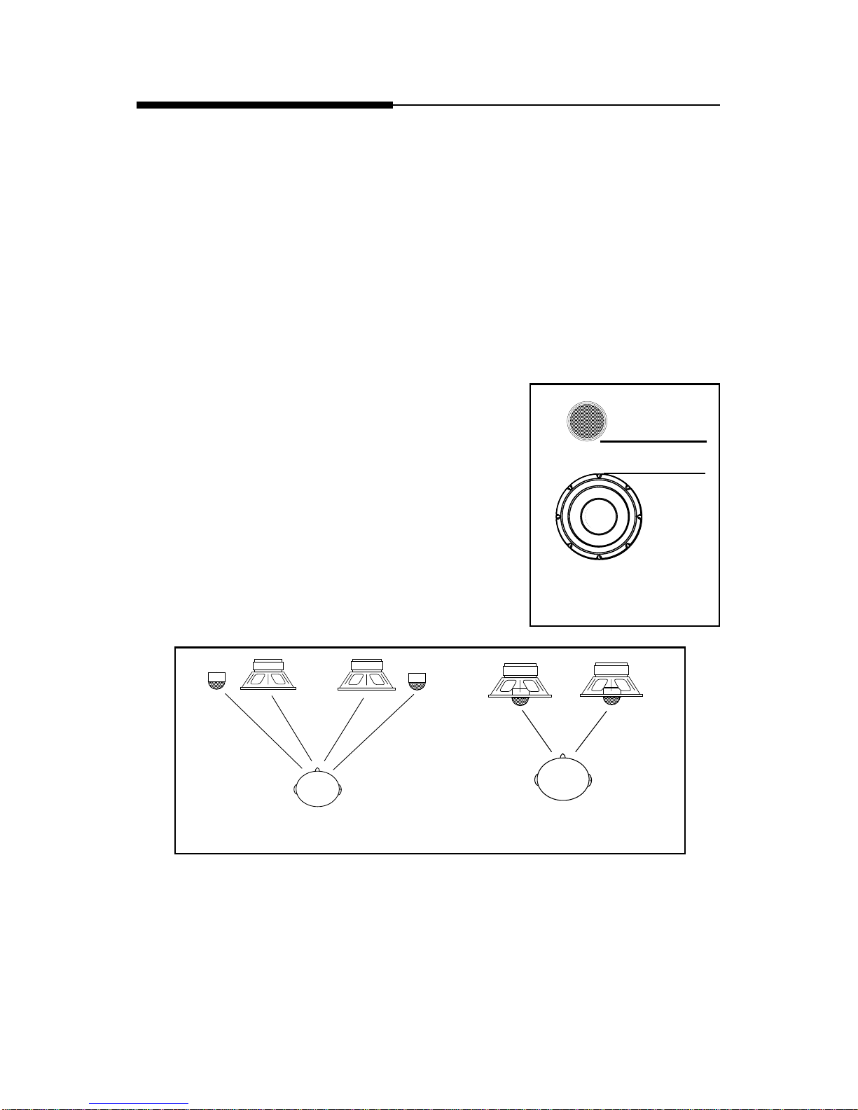
•For the best integration between the midrange and tweeter, the tweeter
should be placed less than 2" from the midrange (Figure 1).
•If you cannot place the tweeter less than 2"
from the midrange, then place the tweeter
more than 7" from the midrange. Placing the
tweeter 2"–7" from the midrange can cause
destructive interference (frequency response
problems) which will affect the speaker's abil-
ity to reproduce the frequency range around
the crossover frequency of the system.
•Whenever possible, place the tweeter direct-
ly above or below the midrange as this max-
imizes the imaging (point source) capability
of the speakers (Figure 2). Figure 1
2" or less
Figure 2-A Figure 2-B
MOUNTING LOCATION
–4 –
between the midrange and tweeter are reduced to a minimum. The result
is a negligible difference in path lengths between the midrange and
tweeter regardless of the proximity of the listener to the speakers.
Mounting the speaker with minimum path length difference will ensure
the best staging and imaging possible from your audio system.
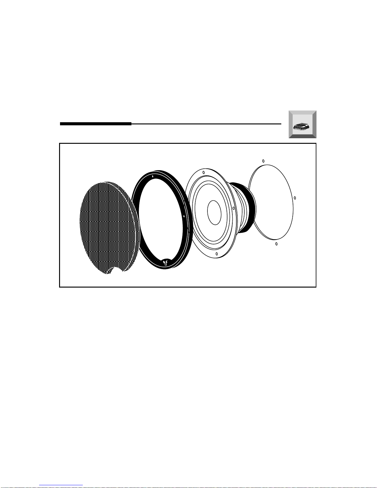
1. Cut the proper size hole for the midrange/woofer.
•For the 4”speaker, cut a 90mm (3
9
⁄
16
") diameter hole
•For the 5-1/4”speaker, cut a 114mm (4
15
⁄
32
") diameter hole
•For the 6”speaker, cut a 129mm (5
1
⁄
16
") diameter hole
•For the 6-1/2”speaker, cut a 139mm (5
1
⁄
2
") diameter hole
2. Place the mounting ring over the mounting hole and mark the location of
the screw mounting holes.
3. Remove the ring. Drill the holes for the screws using a 1/8" drill bit.
4. Route the wire through the hole.
5. Attach the wires and be sure to observe the proper speaker polarity.
6. Place the mounting ring over the speaker.
7. Place the speaker into the hole and screw the speaker into place. Be care-
ful not to bend the speaker frame during this step.
8. Press the speaker grille into the mounting ring.
Mounting the Midrange
INSTALLATION
I
N
S
T
A
L
L
A
T
I
O
N
+ -
+ -
–5 –
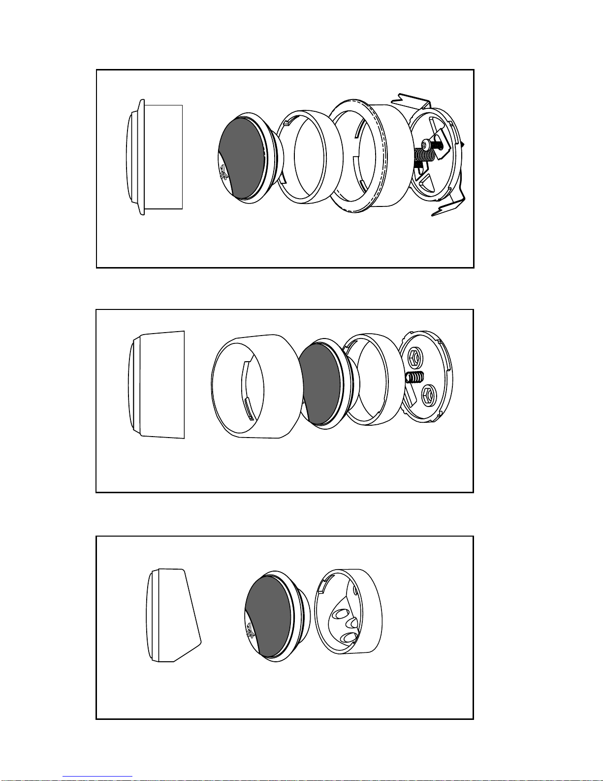
Flush Mount Tweeter
Tweeter
Surface Mount Tweeter
Trim
Ring Back
Plate
Flush
Housing
Tweeter Trim
Ring Back
Plate
Surface
Housing
Wedge Mount Tweeter
Tweeter Wedge
Housing
–6 –
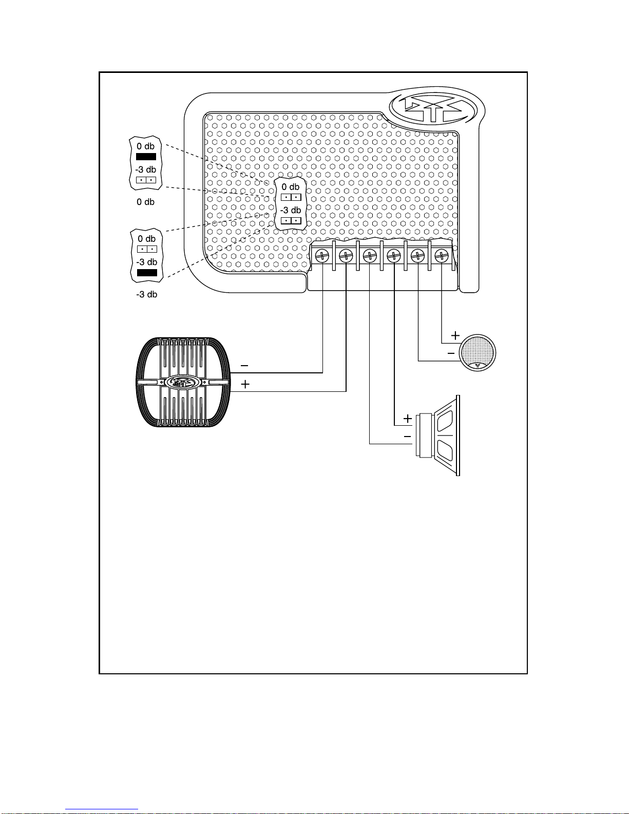
•Be sure to maintain speaker polarity
•0dB Tweeter Level matches the amplitude of the tweeter to the midrange
•-3dB Tweeter Level reduces the amplitude of the tweeter -3dB lower than the
midrange. (ex. ideal for tweeters located high in door panels and midranges located
low in the kick panel)
•Replaceable Tweeter Protection Bulb acts as a fuse to protect against overload. If the
bulb burns out, remove the burned out bulb and insert a new bulb (part# HDW10932)
into the retainer clips.
Crossover Connections Model 242X
–7 –
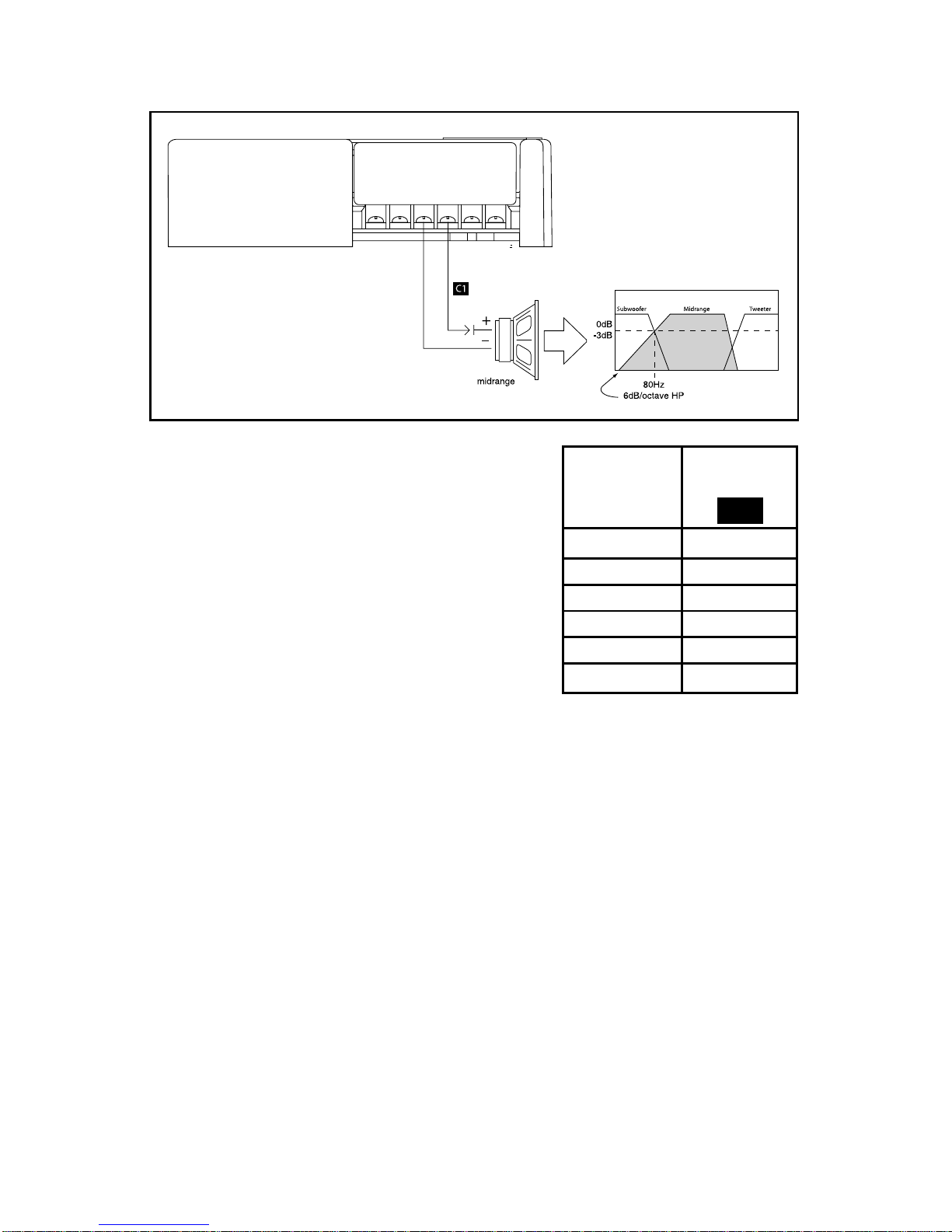
The Fanatic Component Systems are opti-
mized for full range music reproduction. In
cases where a subwoofer is used, the
midrange can be bandpassed in order to pre-
vent overlapping frequencies from the
midrange into the subwoofer.
1. Determine the frequency range that the sub-
woofer will play (i.e.: 20Hz–80Hz)
2. Use the low-pass crossover frequency of
the subwoofer system (i.e.: 80Hz) as the
high-pass crossover frequency for the
midrange
3. Select the appropriate capacitor value (i.e.: 500µF) to properly bandpass
the midrange
4. Place the capacitor in series with the “+”terminal of the speaker
80Hz 500µF
100Hz 400µF
130Hz 300µF
200Hz 200µF
260Hz 150µF
400Hz 100µF
Frequency Speaker
(Hertz) (4 ohms)
C1
Bandpassing the Midrange
Ce manuel convient aux modèles suivants
3
Table des matières
Autres manuels Rockford Fosgate Système de haut-parleurs


Manuels Système de haut-parleurs populaires d'autres marques


Sondpex
Sondpex Active Speaker System and Digital Music... Manuel utilisateur

JVC
JVC NX-PN7 Manuel utilisateur

Marshall Amplification
Marshall Amplification AR-DM61-BT Manuel utilisateur

Yamaha
Yamaha NX-A01 - Speaker Sys Manuel utilisateur

SE Audiotechnik
SE Audiotechnik I-LINE Manuel utilisateur

Gemini
Gemini WRX-843 Series Manuel utilisateur