Roam RoamView Manuel utilisateur

ROAMview
Setup Guide

Before You Proceed
1. Make sure that you have a copy of the ROAMview Installation Worksheet, System
Information Requirements and Onsite Service Request forms.
2. If you do not have these documents, then you can download them at
www.roamservices.net under the Documentation tab.
3. Use the Installation Worksheet to notate the MacID of each node and DCM, the location
of the devices by way of Pole/Fixture ID notations and other required attributes.
4. When you are ready to schedule startup, submit the following completed forms to
a. System Information Requirements
b. Installation Worksheet
c. Onsite Service Request Form
d. Map Image of Deployment Area
5. If you have questions, please call Technical Assistance at 1-800-535-2465

Contents
Introduction
Network Configuration
ROAMview Server Installation
Gateway Installation
Node Installation
Technical Assistance
4
5
9
10
12
14
Appendix A
Hardware Components
System Requirements
15

4
Introduction
Welcome to the ROAMview Setup Guide. This document will cover the three configuration options and the
hardware installation. It is recommended that you first take a quick read of this entire booklet and determine
whether or not you feel comfortable performing the installation. If you have any questions or concerns about
the installation, please do not hesitate to call us for assistance. Our contact information is in the back of
this guide. Our goals are to ensure that your system will function as designed and that you have a pleasant
experience when using it. An improper installation can interfere with these goals. The next section describes
the three configuration options.
5
Network Configuration
Selecting a Configuration
The ROAMview system allows for three methods of connecting the Gateway and ROAMview Server. Please read
through the options and select one of the following configurations for your installation.
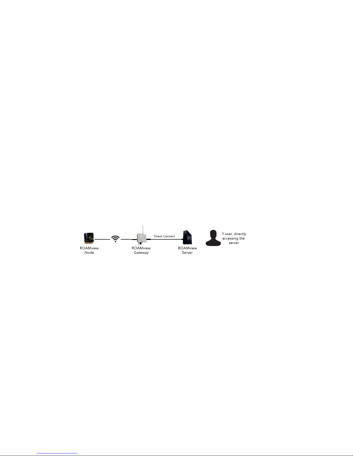
Configuration A
In this configuration, the Gateway is wired to the ROAMview Server by directly connecting an Ethernet cable between the
two; keep in mind the Ethernet cable should not exceed 300 feet. When using this method, the ROAMview Portal (user
interface) will only be accessible through direct use of the ROAMview Server.
This option is recommended for users without an existing network or for those who don’t need to integrate the
ROAMview system with their existing network.

6
Configuration B
This configuration connects the Gateway and ROAMview Server together as described in Configuration A;
however, the ROAMview Server is also connected to the end user’s existing network. This enables the ROAMview
Portal to be accessed by other computers on the network.
This option works well for users who mount the Gateway on the same building as the ROAMview Server and want the
flexibility of interacting with the ROAMview Portal through other computers on the network.

7
Configuration C
In this configuration, both the Gateway and the ROAMview Server are wired to the end user’s network. As long
as the ROAMview Server and Gateway are on the same subnet, they will communicate as required.
This option works well for users who need to mount the Gateway(s) over 300 feet away from the ROAMview Server. Users
will be able to interact with the ROAMview Portal through other computers on the network.

8
System Information Requirements
After selecting a network configuration, you should be ready to complete the System Information Requirements
Sheet. This document needs to be filled out and sent in with your chosen configuration and the corresponding
network information (you may need to consult with the network administrator to collect required network
information). Please refer to the document for information on how to submit. If you do not have a copy of
the System Information Requirements sheet, you can download the form at www.roamservices.net under the
Documentation tab. This document must be submitted before on site startup can be scheduled.

9
ROAMview Server Installation
Setup
The initial setup will be much like setting up a standard desktop computer.
1. Locate a suitable place to install the ROAMview Server. A server room
or desk of a frequent user are the most common locations.
2. Plug the power cord into the ROAMview Server.
3. Plug the keyboard and mouse into the USB ports on the ROAMview
Server.
4. Plug a monitor (not provided) into the ROAMview Server.
5. Plug in the Ethernet cable.
a. Configuration A or B: Ethernet cable from Gateway should be
connected to the USB network adapter (provided). Then plug the
USB network adapter into a USB port on the ROAMview Server.
b. Configuration C: Ethernet cable should be connected directly
from the network port on the ROAMview Server to a port on the
existing network. Contact your IT manager for assistance on
making this connection.
6. Press the power button on the machine to verify the log-in screen is
displayed.

10
Location Recommendations
The Gateway should be mounted outdoors and centrally located within the node deployment.The gateway
should not exceed 1,000 feet line-of-sight to the closest nodes; however, less than 500 feet to the closest nodes
is preferable.
Mounting
The Gateway may be mounted using a pole or directly to a suitable flat surface. In either case, the Gateway must
be mounted where the screw-on antenna points up and the indicator LED points down.
Pole Mounting
Use the supplied universal mount, articulating bracket and hardware to
attach to pole or pipe. The diameter of the pole or pipe must be between
1 and 3 inches.
Surface Mounting
Remove pole/pipe bracket coupling from the universal mount and secure
the arm directly to the surface using four ¼ inch bolts.
Gateway Installation
Table des matières


