RMG RMG 610 Mode d’emploi

Osterholzstraße 45, D-34123 Kassel • P.O. Box 10 29 67, D-34029 Kassel
Phone 0049 561 5007-0 • Fax 0049 561 5007-107 • www.rmg.de
Operation and Maintenance 610.20
Spare Parts Edition 02/96
Pilot (RS 10d)
RMG 610
... providing all components you
need for reliability in gas supply

Table of contents
1.
2.
2.1
2.2
3.
3.1
3.2
3.3
3.4
4.
4.1
4.2
4.3
4.4
5.
5.1
5.2
5.3
General Instructions
Special Operation Instructions
Adjustment of the auxiliary pressure
Adjustement of the discharge valve
Special Maintenance Instructions
Auxiliary pressure stage
Control stage
Torque
Lubricants
Spare Parts Drawings RMG 610
Spare parts drawing RMG 610 with control stage tool N
and pilot intermediary part
Spare part drawing RMG 610 with pilot and auxiliary pressure stage
tool M
Spare parts drawing RMG 610
- Sleeve for auxiliary pressure stage with lever joint
- Spindle for discharge valve
- Lever bearing
Spare parts drawing pressure regulator for auxiliary pressure stage with
spare parts list
Spare Parts Lists
Spare parts list RMG 610
Spare parts list RMG 610
Spare parts list RMG 610
3
4
4
5
5
5
5
6
6
7
7
8
9
10
11
11
12
13
Seite
!Attention
... providing all components you
need for reliability in gas supply

1. General
Our leaflet 610.00 gives full information with technical data , different versions and dimensions of the pilot
RMG 610 (RS 10d).
Our brochure "General Operating Instructions for Gas Pressure Regulators and Safety Devices" will be
useful to fit the valve into the line, put it into service and find faults that might disturb its operation.
The construction, set-up, supervision and maintenance of gas pressure regulating stations are subject to
special technical rules which should be strictly observed, in particular those given by the DVGW Worksheets
G 490, G 491, and G 495.
The frequency of periodical maintenance to be foreseen for the safety shut-off valve RMG 711 should be
determined according to the prevailing service conditions and the type and composition of the gaseous
medium. We, therefore, abstain from imposing any fixed intervals and would rather refer you to the recommen-
dations given by the DVGW Worksheet G 495.
For maintenance all parts are to be cleaned and subjected to a thorough visual inspection. A visual inspection
should not be omitted when the course of operation or performance tests have shown lack of response
accuracy. Particular care should be given to the checking of sealings and diaphragms, as well as of all carrying
and movable parts, engagement and release systems of the tripping and measuring devices and of closing springs.
Damaged parts should be replaced by new ones.
The item numbers referred to in the maintenance instructions are identical with those of the spare parts drawings and
spare parts lists.
We recommend to keep all parts that are specially marked in the spare parts lists in stock for prompt maintenance
availability.
610.20 p. 3
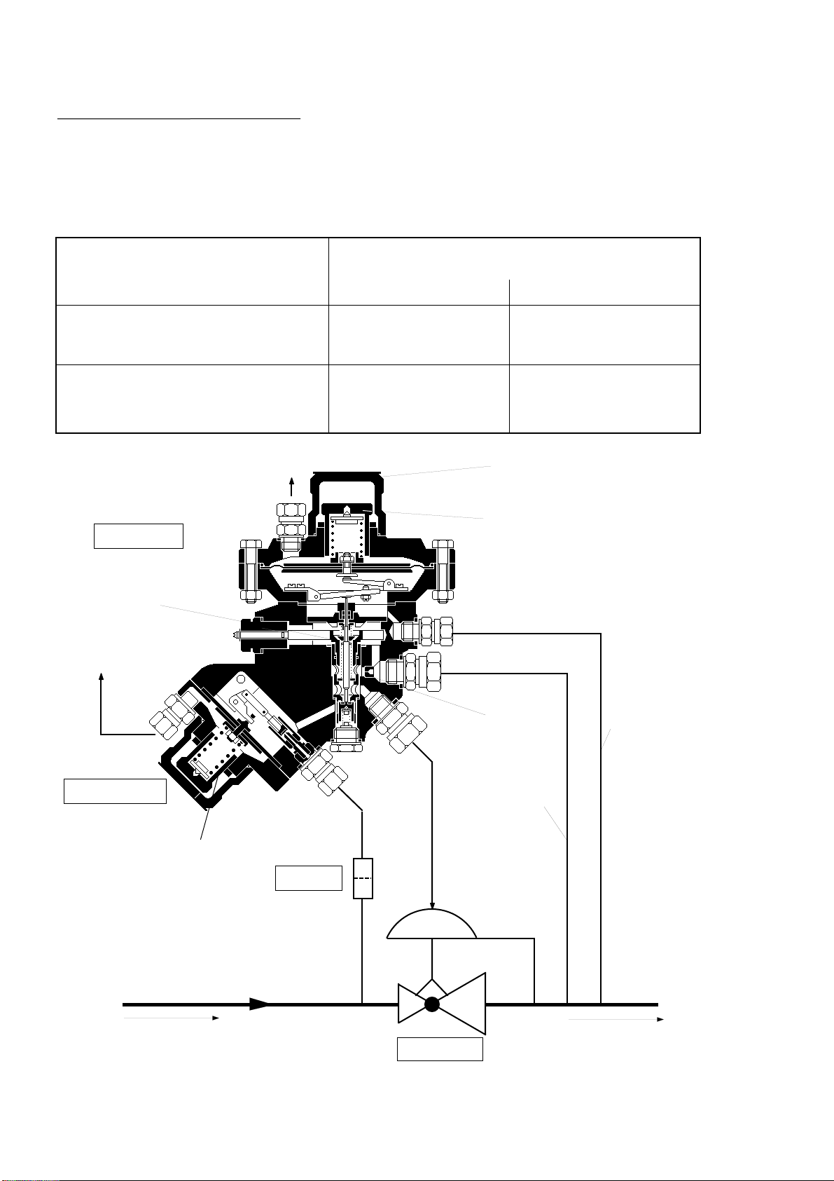
Principal switch drawing of the pilot RMG 610 (RS 10d) with a switch gear
control stage
auxiliary stage
main valve
adjusting pressure
measuring line
discharge
line
discharge
throttle
setpoint adjuster
for auxiliary pressure
breathing line
breathing line
setpoint adjuster for outlet pressure
inlet pressure p outlet pressure p
ea
discharge valve
610.20 p. 4
gas pressure regulation unit
used in a pressure regulation device:
with direct following high guide network,
f.i. hand over stations
with direct following second pressure or
flow regulation valve, f.i. in a heat gas line
height of the auxiliary pressure over the
outlet pressure with a main valve
RMG 322, 332, 408, 409
approx. 1 - 2 bar
approx. 0,5 - 1 bar
RMG 200
approx. 2 - 4 bar
approx. 1 - 2 bar
2. Special Operation Instructions
2.1 Adjustment of the auxiliary pressure
The height of the adjusted auxiliary pressure influences the regulating procedure of the device.
To obtain a high precision of regulation, which is connected to a smaller closing pressure, an auxiliary pressure should be
adjusted as high as possible in the stabilization of the gas pressure regulation device.
According to the application the following advised values must be appplicated:
fine filter
protection cap

2.2 Adjustment of the discharge valve
The discharge valve is delivered from the plant with the main
adjustment. The necessary rotation of the spindle for this
adjustment is given on the picture situated on the pilot (see
drawing on the right).
By turning the spindle left to the bleed adjustment " - ", it is
possible to adapt the device to special operation instructions
-additionally to change the auxiliary pressure-
f.i. by regulation variations of "pressure picks" after a quick
closing of the stop organ preswitched.
Verstärkungseinstellung
Bleed adjustment
Adjustage d`amplification
X=
Grundeinstellung:
Linksdrehen bis Anschlag
X Umdrehungen nach rechts
Basic adjustment:
Turn anti-clockwise to the stop
turn spindle X times clockwise
Adjustage de base:
Tournez à gauche jusqu à l `arre
t
Apres à droite par X tours
610.20 p. 5
rotation
adjusting spindle
3. Special Maintenance Instructions
3.1 Auxiliary pressure stage (see page 8)
Diaphragm (68)
By dismantling, put the cover (69) off, put the diaphragm (68) on the side of the inlet pressure connection and
hang the diaphragm on the side outside the joint (80).
Sealing cone (81)
To dismantle the sealing cone, the screws (98) must be unscrewed and the complete joint (80)
must be put off. A mark of the sleeve corner (83) on the sealing surface of the sealing cone (81) is normal.
By installing the sealing cone, the position of the lever joint must be controlled after the installation of the joint and
newly adjusted if necessary.
The correct adjustment is given if the lever is manually put out (piston in closing position) and the superior corner of
the lever is parallel to the diaphragm support.
A possible and necessary correction is obtained by underlaying the different thicker sealing rings (51, 85) under the
intermediary piece.
3.2 Control stage - Tool M and N (see p. 6 and 8)
Control rod (16, 76)
The control rod must lightly slide in its conduction. By installing the new parts in the outlet pressure stage the
adjustment measure of the rod must be controlled according to the measurement tool and be corrected if necessary.
The adjustment measure must be put off according to the following drawing.
Adjustment measure for control stage tool N

610.20 p. 6
Beware:
Piston (23)
The piston of the control stage must lightly slide in its conduction.
The measure controls occur for an incorporated control pin (16, 76), that is to say the control rod
(20) is on the piston (23), the sleeve is still closed. The control rod is delivered with an excessive
length and must for this reason be shorted by replacing corresponding to the adjustment measure
and lastly borderless rounded .
3.3 Torque
30
2,5
3.4 Lubricants
part (to be greased slightly )
all o-rings,
all sliding surfaces and movable parts
adjusting screw (44, 116)
spring plate thread and recession
all fastening and
pipe screws
lubricant
silicone grease
mounting paste
high pressure
grease
part no.
00 027 081
00 027 091
00 027 058
(9)
(4)
Adjustement measure for control stage tool M
pos. no. torque
M in Nm
a

4. Spare Parts Drawings
4.1 Spare Part Drawing RMG 610 (RS 10d)
Pilot intermediary part with control stage tool N
610.20 p. 7
* Parts marked by an asterisk to be kept in stock maintenance
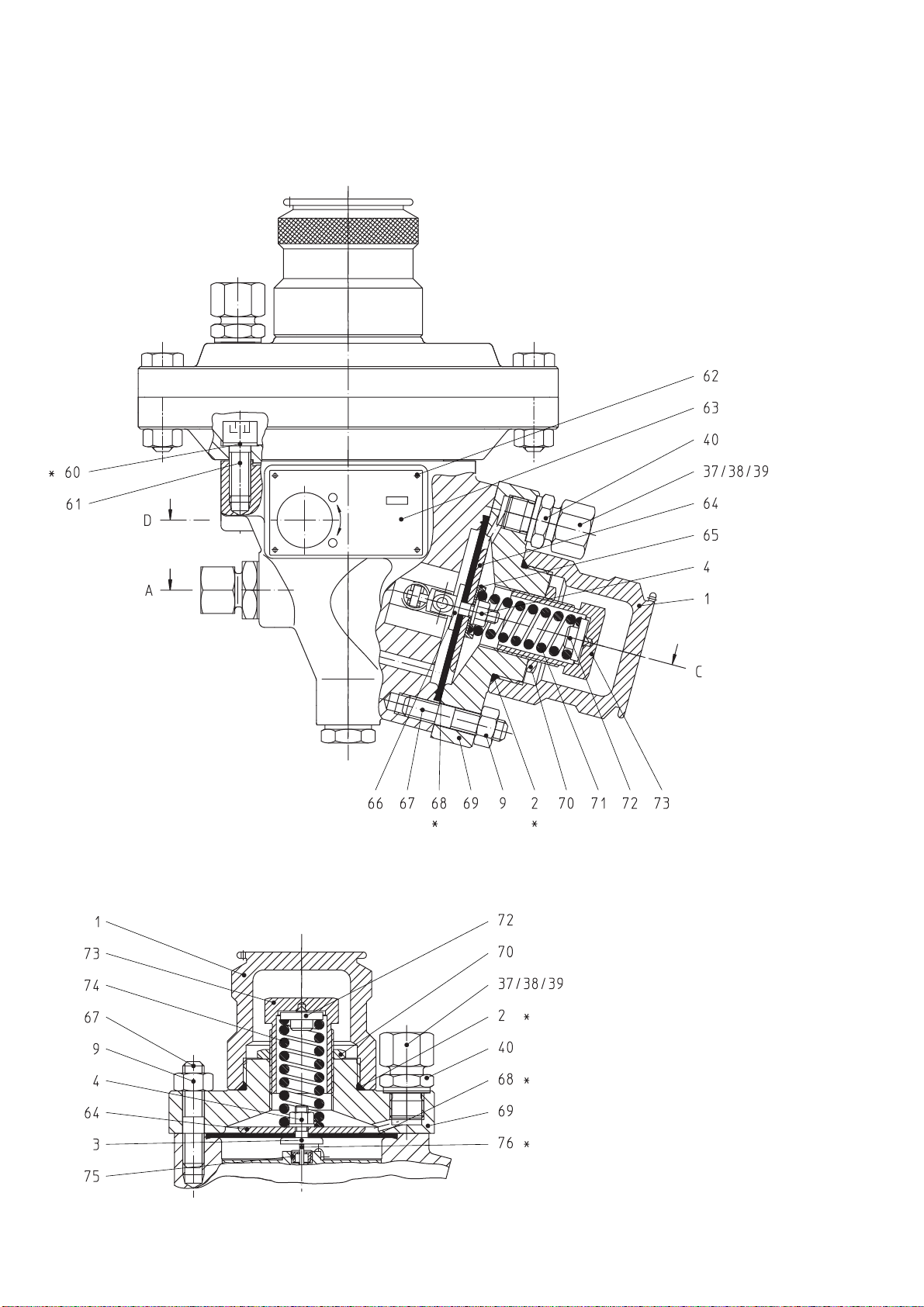
4.2 Spare Parts Drawing RMG 610 (RS 10d)
Control stage tool N, auxiliary pressure stage tool M
Control stage tool M
* Parts marked by an asterisk to be kept in stock for maintenance
610.20 p. 8

4.3 Spare Parts Drawing RMG 610 (RS 10d)
* Parts marked by an asterisk to be kept in stock for maintenance 610.20 p. 9
Sleeve for auxiliary pressure stage with lever joint
Sectional view A - C
Spindle for discharge line
partial view D Lever bearing
sectional view E - E

4.4 Spare Parts Drawing RMG 610 (RS 10d)
Pressure measuring unit for auxiliary pressure stage
pos. no.
150
151
152
153
154
description
pressure measuring unit
manometer union piece
protection against overpressure RMG 925
cap nut
compression joint
material
St/Ms
St
LM
St
St
part no.
pressure stage of the main valve
PN 16 PN 25 > PN 25
00 026 891
00 031 865
-
00 030 803
00 030 903
00 026 891
00 031 865
-
00 030 803
00 030 903
00 026 281
-
89 251 406
-
-
610.20 p.10
Material - key:
St
LM ... steel
... light metal Ms ... brass
Table des matières
Autres manuels RMG Contrôleurs

RMG
RMG 330 Mode d’emploi

RMG
RMG 214 Mode d’emploi

RMG
RMG AWLC-110-000 Manuel utilisateur

RMG
RMG EC 24 Manuel utilisateur

RMG
RMG DRTCC Manuel utilisateur

RMG
RMG WAWLCI -TS Manuel utilisateur

RMG
RMG AWFAWLC-044 Manuel utilisateur

RMG
RMG 672 Mode d’emploi

RMG
RMG 503 Manuel utilisateur

RMG
RMG DFAWLC-044 Manuel utilisateur


