RITE-HITE CoolMan 2800 Manuel utilisateur
Language: English (Hazards: English, French)
NOTICE TO USER . . . . . . . . . . . . . . . . . . . . . . . . . . 2
SAFETY. . . . . . . . . . . . . . . . . . . . . . . . . . . . . . . . . . . 2
Lockout Procedure . . . . . . . . . . . . . . . . . . . . . . . . . . . 3
INSTALLATION
Preparation. . . . . . . . . . . . . . . . . . . . . . . . . . . . . . . . . 4
Telescoping Support Arm . . . . . . . . . . . . . . . . . . . . . . 5
Wall Bracket Position (STANDARD) . . . . . . . . . . . . . . 6
Wall Bracket Adjustment (OPTIONAL) . . . . . . . . . . . . 7
Wall Bracket / Support Arm . . . . . . . . . . . . . . . . . . . . . 8
Fan Mounting Bracket . . . . . . . . . . . . . . . . . . . . . . . . 8
Secure Power Cords . . . . . . . . . . . . . . . . . . . . . . . . . 9
OPERATION
Fan Controls. . . . . . . . . . . . . . . . . . . . . . . . . . . . . . . 10
Light Controls . . . . . . . . . . . . . . . . . . . . . . . . . . . . . . 11
Positioning . . . . . . . . . . . . . . . . . . . . . . . . . . . . . . . . 13
MAINTENANCE . . . . . . . . . . . . . . . . . . . . . . . . . . . 13
PARTS
CoolMan®2800 Trailer Fan
with Rite-Lite™ LED Dock Light . . . . . . . . . . . . . . . . 14
LED Light and Controls . . . . . . . . . . . . . . . . . . . . . . 14
WARRANTY . . . . . . . . . . . . . . . . . . . . . . . . . . . . . . 16
Model: COOLMAN2800
Manual Part #: 54450060
Publication: AMEN00262 2019-12-09
CoolMan®2800 Trailer Fan
with Rite-Lite™ LED Dock Light
Installation/Service/Owner's Manual
NOTICE TO USER
READ AND SAVE THESE INSTRUCTIONS.
Thank you for purchasing a Rite-Hite®product.
The CoolMan®2800 Trailer Fan with Rite-Lite™ LED Dock
Light oers enhanced exibility and adjustability when
cooling and lighting a trailer or container at the loading
dock.
The English version of this manual shall prevail over any
error in, or conicting interpretation of, any translations.
Rite‑Hite reserves the right to substitute and/or modify
parts and drawings. If separate prints are included with
the unit, they supersede those contained in the manual.
For best results, have this product serviced by an
authorized Rite-Hite representative.
A Planned Maintenance Program (P.M.P.), customized to
your specic operation is available and recommended.
For a P.M.P., contact your local Rite-Hite representative
or Rite-Hite technical support at (U.S.) 1-414-973-3625
or 1-888-456-3625, (S.A.) +55 21 99616 4421,
(E.U.) +49-5693 98700.
The Rite-Hite® products in this manual are covered by one or more
of the following U.S. patents: D693947, D701640, D702397, US9255699
and may be covered by additional pending U.S. and foreign patent
applications.
Manufactured by Rite‑Hite Engineered Solutions Group, Inc.
SAFETY
Safety Identifications
DANGER
Indicates a hazardous situation which, if not
avoided, will result in death or serious injury.
Indique une situation dangereuse qui, si elle n’est
pas évitée, peut entraîner la mort ou de graves
blessures.
WARNING / AVERTISSEMENT
Indicates a hazardous situation which, if not
avoided, could result in death or serious injury.
Indique une situation dangereuse qui, si elle n’est
pas évitée, peut entraîner la mort ou des blessures
graves.
CAUTION / ATTENTION
Indicates a hazardous situation which, if not
avoided, could result in minor or moderate injury.
Indique une situation dangereuse qui, si elle n’est
pas évitée, peut entraîner des blessures légères à
modérées.
NOTICE
Indicates a situation which can cause damage to the
equipment, personal property and/or the environment,
or cause the equipment to operate improperly.
NOTE:A note is used to inform you of important
installation, operation, or maintenance information.
CoolMan®2800 Trailer Fan with Rite-Lite™ LED Dock Light Installation/Service/Owner's Manual Rite-Hite®
2 Publication: AMEN00262 2019-12-09
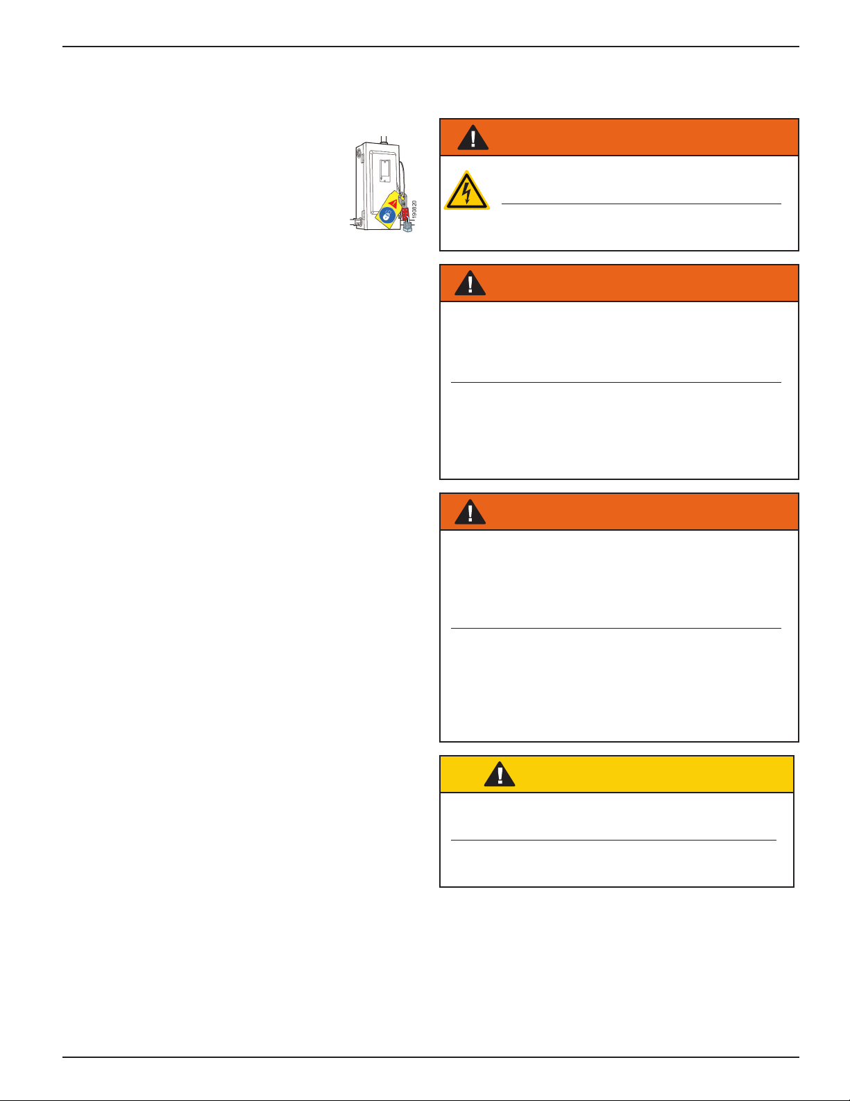
SAFETY
Lockout Procedure
Barricade work area and post safety warnings.
Power supply and control must:
• Be disconnected or locked in OFF position
using a lockout device approved by local
codes.
• Have signage that;
− Clearly states repairs are being made.
− Identies person responsible for lockout condition.
NOTE: Only this person should be able to remove
warnings and lockout device.
−Withstands environmental conditions (weather,
wet, and damp, etc.) and remains readable.
General
WARNING / AVERTISSEMENT
Risk of electrical shock. DO NOT expose to
water or rain.
Risque de choc électrique. NE PAS
exposer à l'eau ou à la pluie.
WARNING / AVERTISSEMENT
Prior to use, visually inspect cord for damage.
Immediately remove unit from service if jacket or
insulation appears frayed, cut, pinched, or crushed,
or if grounding pin is damaged or missing.
Avant l’utilisation, inspecter visuellement le cordon
pour dommages. Enlever immédiatement unité
service si veste ou isolation apparaît elochée,
coupée, pincés ou écrasés, ou si la goupille de
mise à la terre est endommagé ou manquant.
WARNING / AVERTISSEMENT
Use only three wire extension cords that have
three prong grounding plugs and grounding
receptacles that accept the appliance’s plug. Use
only with a hard service extension cord of type SJ,
SJO, SJT, SJTW, or equivalent.
Utiliser seulement des rallonges qui ont trois
broches avec une mise en terre et des récipients
compatibles acceptant la prise de l’appareil.
Utilisez uniquement des rallonges pour usage
intensif de type SJ, SJO, SJT, SJTW ou
équivalent.
CAUTION / ATTENTION
Barricade the work area until the unit(s) have
been completely installed.
Barricader la zone de travail jusqu'à ce que
l'unité(s) ont été complètement installé.
190820
Rite‑Hite®Installation/Service/Owner's Manual CoolMan®2800 Trailer Fan with Rite‑Lite™ LED Dock Light
Publication: AMEN00262 2019-12-09 3
INSTALLATION
The CoolMan 2800 is designed to be mounted in various
ways depending on the requirements of the installation
site. Some eld engineering is allowed. Contact
Rite-Hite technical support at (U.S.) 888-456-3625 or
1-414-973-3625, (S.A.) +55 21 99616 4421, (E.U.)
+49-5693 98700 for assistance with instructions outside
of these guidelines.
The CoolMan 2800 rotates on 3 bolted connections
including the wall bracket, the double arm to single arm
connections, and the swivel clevis.
Preparation
Components
Before installation, verify all components were received.
Notify your Rite-Hite representative if parts are missing
or damaged.
CoolMan 2800 components are shipped in 4 boxes:
1 Fan
1 Support arm assembly
1 Wall mount bracket or 1 adjustable wall mount bracket
1 Fan mount or 1 fan mount with Rite-Lite LED Dock Light
Required Tools
1 Tape measure
1 Diagonal cutter or box knife
1 Bubble level
2 Wrenches 1/2in
2 Wrenches 15/16in
1 Drill
1 Step Ladder
Tools for 4 wall anchors (supplied by others).
Minimum of (4) 1/2in x 3in [12mm x 75mm].
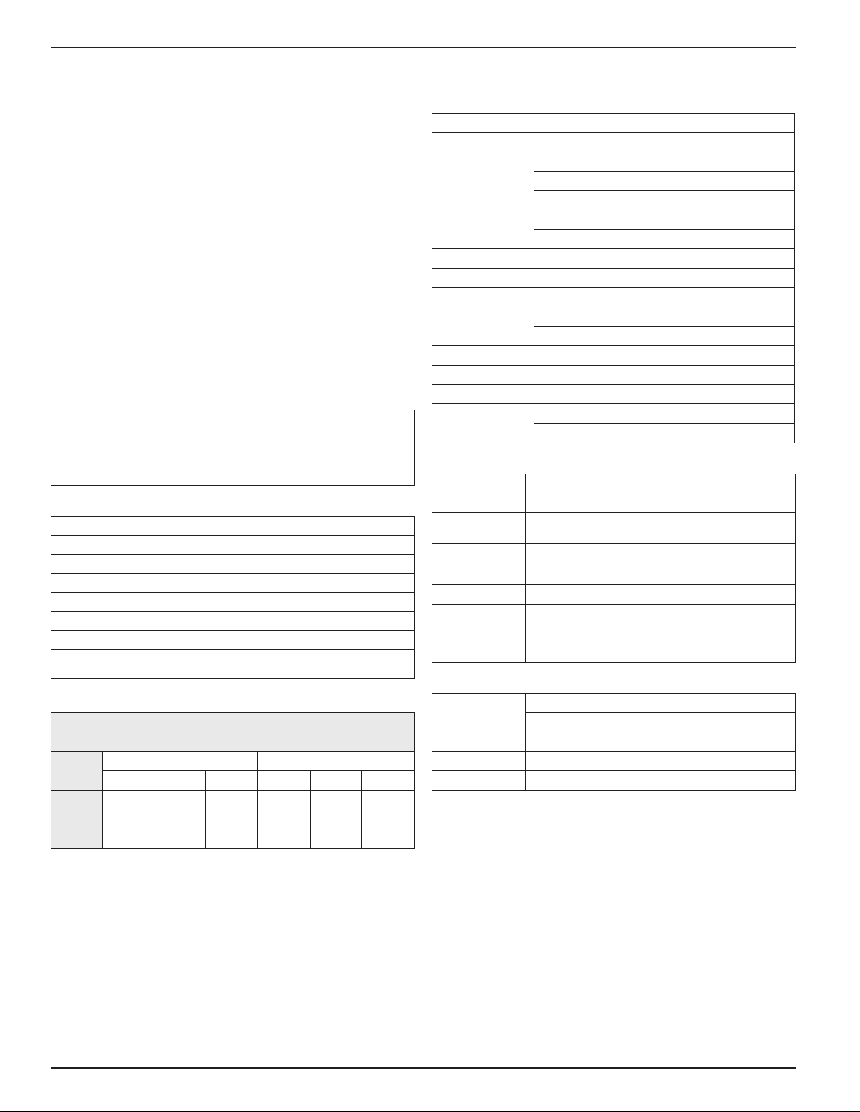
CoolMan 2800 dB(A)
Measured 36.0in [920 mm] from Air Inlet and Motor
Measured 108.0in [2750 mm] from Air Outlet
Switch
Position
115V 60 Hz 220V 50 Hz
Motor Inlet Outlet Motor Inlet Outlet
1 74 78 73 67 72 68
2 81 84 78 74 78 73
3 84 87 81 77 81 76
220 RPM Estimated not measured
Extech 407736 Sound Level Meter
Fan Specications
Size 16in x 16in x 16in [410mm x 410mm x 410 mm]
Weight Wall Bracket 9lb [4kg]
Adjustable Wall Bracket 38lb [17kg]
Support Arm 32lb [15kg]
Fan Mount 7lb [3kg]
Fan Mount with LED 10lb [5kg]
Fan 19lb [9kg]
FLA 5.0 Amps at 115 Volts 60 Hertz
FLA 2.2 Amps at 230 Volts 50 Hertz
CFM 2800 [79 m3/min]
Controls O, Low, Medium, High
Variable 1 ‑ 180 minute auto‑o timer
Power Cord 20ft [6.1m]
Plug NEMA 5-15 (115V) or Schuko CEE 7/7 (230V)
Ingress Protection 40
Approvals ETL / cETL to UL 507 & CSA C22.2 No. 113
CE
Light Specications
Lumens 980
Power 18 watts
Color 3500 “warm” Correlated Color Temperature
IEC 62471 photobiological risk group 1 (low risk)
Controls Dimmable with four intensity settings
Optional motion sensing with auto dimming and
power save
Power Cord 20ft [6.1m]
Plug NEMA 5-15 (115V) or Schuko CEE 7/7 (230V)
Approvals cUL 153
CE
Support Arm Assembly
Size 29in [410mm] double arm swing radius
27in [690mm] single arm swing radius standard
33in [840mm] single arm swing radius extended
Wall Bracket 6in x 16in x 0.25in [155mm x 410mm x 7mm]
Mounting Holes 4.5in x 14.5in x 0.5in [115mm x 370mm x 13mm]
CoolMan®2800 Trailer Fan with Rite-Lite™ LED Dock Light Installation/Service/Owner's Manual Rite-Hite®
4 Publication: AMEN00262 2019-12-09
INSTALLATION
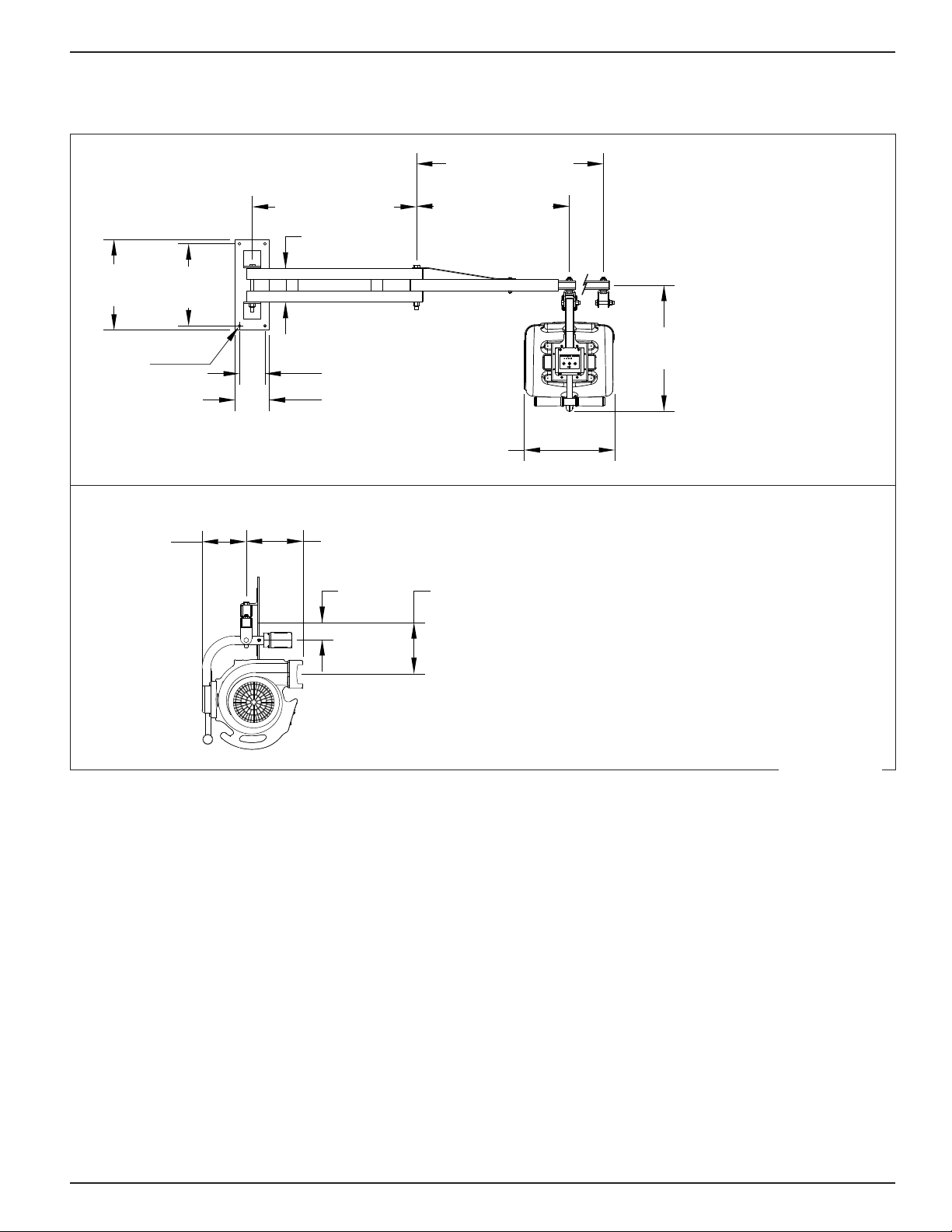
Telescoping Support Arm
29.00in [740mm] 27.00in [685mm]
Standard
33.00in [840mm]
Extended
16.00in
[410mm]
14.50in
[370mm]
6.00in [155mm]
4.50in [115mm]
6.00in [155mm]
22.25in
[565mm]
0.50in
[13mm]
16.00in
[405mm]
<Fan Dimensions Front 2019-05-22pdf.pdf>
Front View
Extended
Standard
Side View
10.00in
[255mm]
7.75in
[195mm]
3.00in
[75mm]
9.00in
[230mm]
<Fan Dimensions Side 2019-05-01.pdf>
The support arm can be extended 6in [155mm] to
compensate for obstructions aecting the wall bracket or
to utilize the fan on two adjacent loading dock positions.
Remove and replace the 5/16in bolt with nylon lock nut to
adjust the support arm length.
Figure 1
Rite‑Hite®Installation/Service/Owner's Manual CoolMan®2800 Trailer Fan with Rite‑Lite™ LED Dock Light
Publication: AMEN00262 2019-12-09 5
INSTALLATION
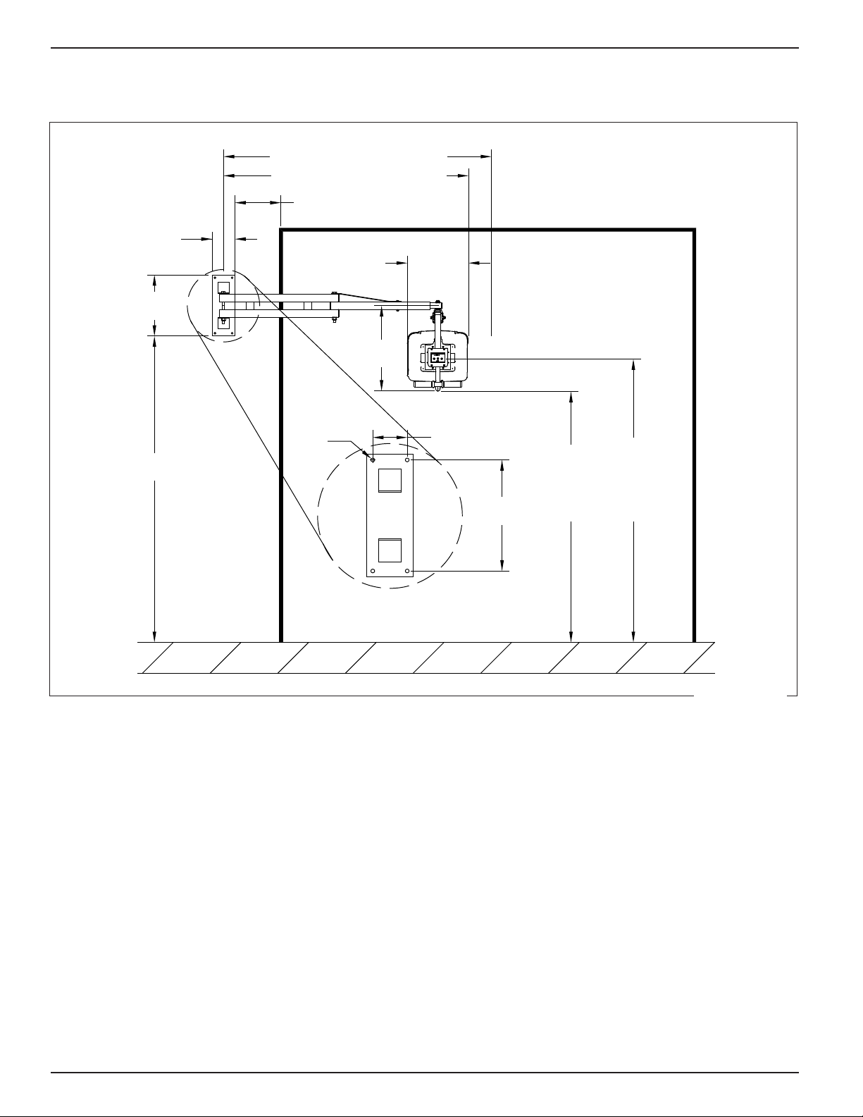
Wall Bracket Position (STANDARD)
16.00in
[410mm]
12.00in
[305mm]
22.25in
[565mm]
6.00in
[155mm]
0.50in
[13mm]
64.00in [1630mm]
80.00in
[2035mm] Clearance
to Floor
65.50in
[1665mm]
14.50in
[370mm]
4.50in [115mm]
16.00in
[410mm]
Light
Controls
74.00in
[1880mm]
70.00in [1780mm]
<Fan Std Bracket Dimensions 2019-05-22.pdf>
Clearance
to Floor
Light
Controls
70.00in [1780mm] Extended
12.00in [305mm]
64.00in [1625mm] Standard
Figure 2
CoolMan®2800 Trailer Fan with Rite-Lite™ LED Dock Light Installation/Service/Owner's Manual Rite-Hite®
6 Publication: AMEN00262 2019-12-09
INSTALLATION
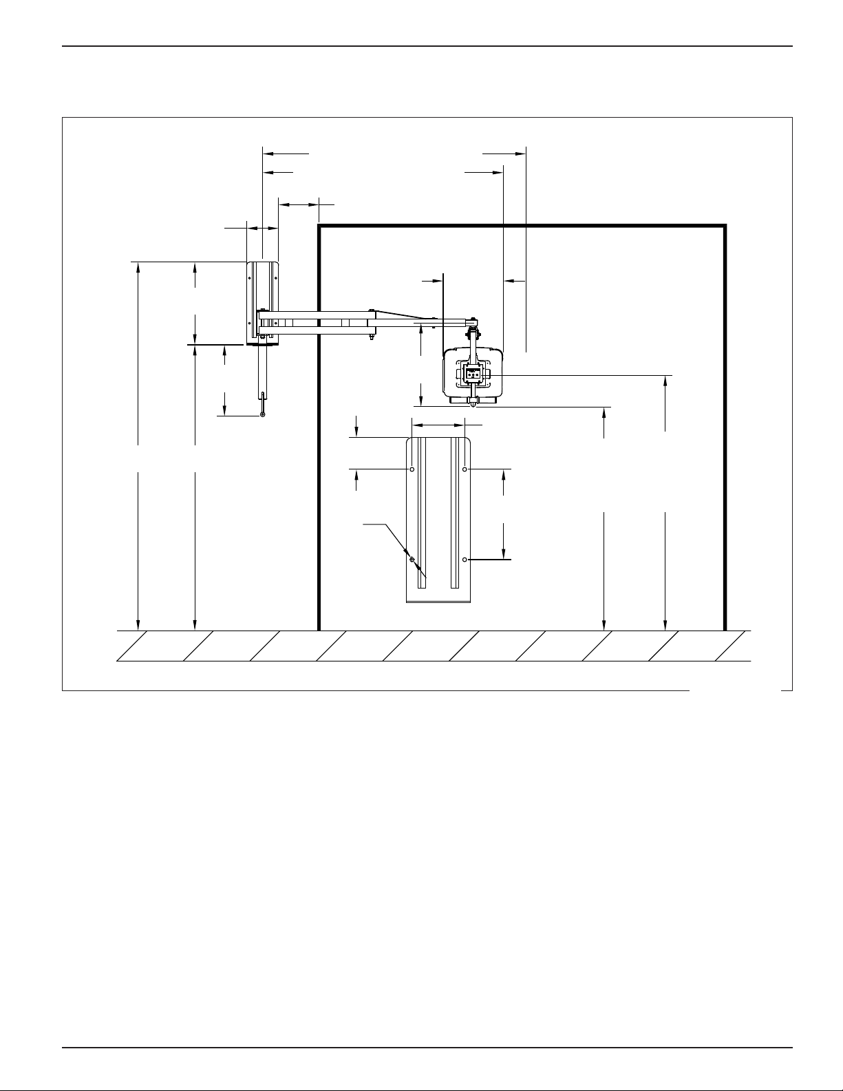
Wall Bracket Adjustment (OPTIONAL)
22.00in
[560mm]
10.75in
[2735mm]
22.30in
[570mm]
76.00in
[1930mm]
12.00in
[305mm]
8.50in
[220mm]
Ø0.50in
[13mm]
64.00in [1630mm]
16.00in
[410mm]
19.00in
[485mm]
4.25
[110mm]
7.00in [180mm]
Clearance
to Floor
59.50in
[1515mm]
Light
Controls
68.00in
[1730mm]
ADJUSTABLE WALL BRACKET DETAIL
70.00in [1780mm]
98.00in
[2490mm]
<Fan Adj Bracket Dimensions 2019-05-22.pdf>
Clearance
to Floor
Light
Controls
Adjustable Wall Bracket Detail
70.00in [1780mm] Extended
64.00in [1625mm] Standard
10.75in [2735mm]
The fan is shown in the lowest position and can be
adjusted upward 12in [305mm].
The recommended adjustable wall bracket location will
position the fan in the same location as the standard wall
bracket when the fan is half way up.
Adjust the mounting location to accommodate employees,
wall obstructions, or dierent trailer heights.
Figure 3
Rite‑Hite®Installation/Service/Owner's Manual CoolMan®2800 Trailer Fan with Rite‑Lite™ LED Dock Light
Publication: AMEN00262 2019-12-09 7
INSTALLATION
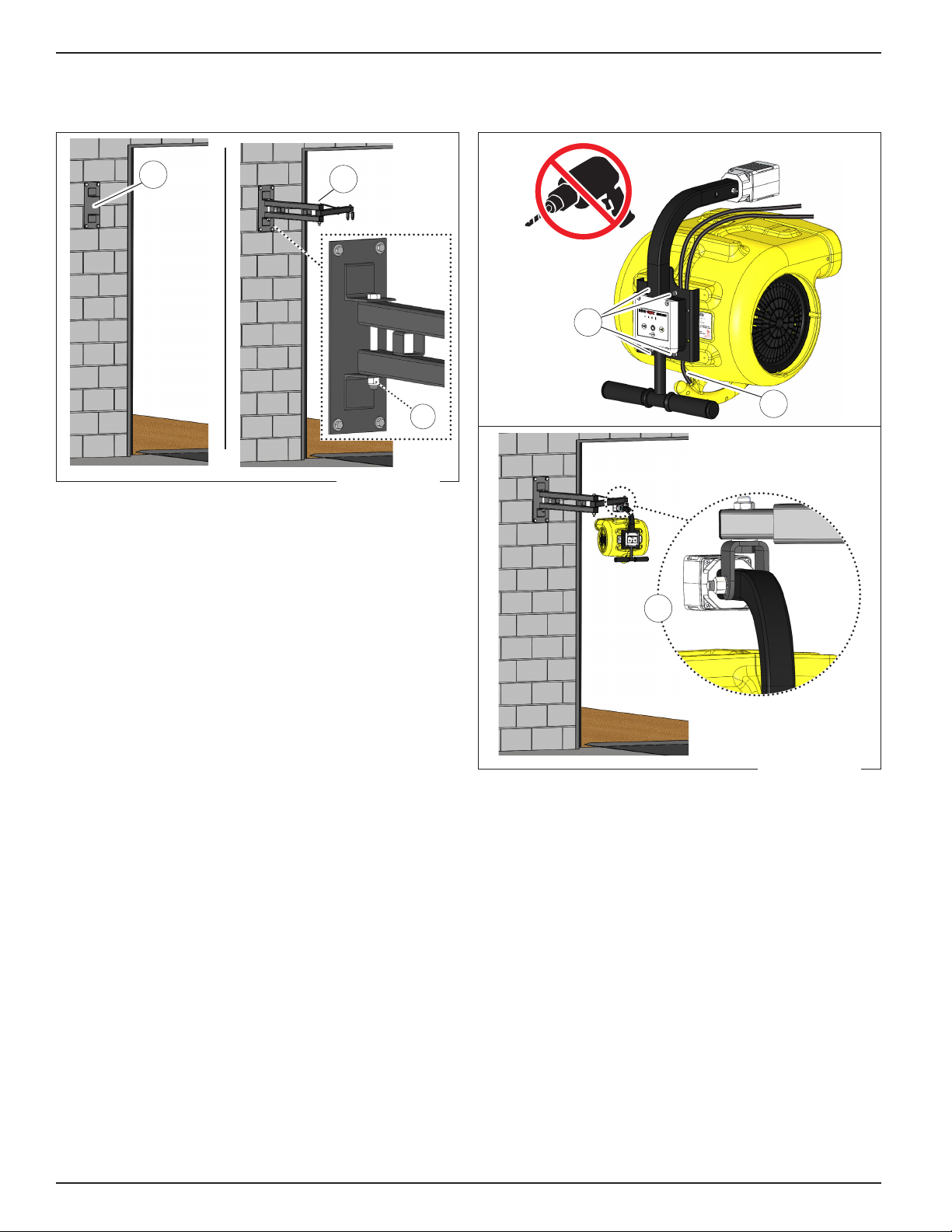
Wall Bracket / Support Arm
A B
C
Use the wall bracket (A) to locate and mark the 4 anchor
hole locations.
1. Drill 1 of the upper wall bracket holes.
2. Anchor the wall bracket to the wall using
1 of the 3/8in [10mm] x 3in [75mm] wall anchors
(supplied by others).
3. Use a bubble level to plumb the wall bracket. Use the
holes as a template to install the remaining anchors.
4. Attach the support arm assembly (B) to the wall
bracket using one 5/8in x 7 1/2in bolt with nylon
locknut (C).
5. Tighten the wall bracket nut secure enough to cause
some friction in the support arm assembly movement.
Fan Mounting Bracket
E
D
F
1. Position the power cord (D) between the fan and
mounting bracket.
2. Attach the mounting bracket to the fan by hand
starting and tightening 4 M6x40 socket head cap
screws (E).
3. Install the fan with mounting bracket to the swivel
clevis (F) using (1) 1/2in x 3in bolt, 2 external tooth
lock washers, and (1) 1/2in nylon lock nut.
4. Tighten the hardware at the wall bracket, at the
double support arm, and at the swivel clevis to
achieve the desired positioning resistance.
Figure 4
Figure 5
CoolMan®2800 Trailer Fan with Rite-Lite™ LED Dock Light Installation/Service/Owner's Manual Rite-Hite®
8 Publication: AMEN00262 2019-12-09
INSTALLATION
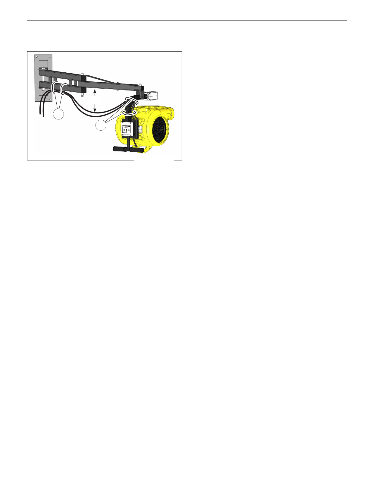
Secure Power Cords
G
H
8in - 10in
[205mm ‑ 255mm]
1. Secure the power cord(s) above and below the
curved area of the fan mounting bracket with 2 tie
bands (G).
2. Move the support arm to a straight position with the
fan perpendicular to the steel tubes.
3. Secure the power cord(s) to the bottom of the double
support tube with 2 tie bands (H). Locate the tie bands
in the center area between the two spacer tubes.
4. Plug the cord into a nearby outlet.
5. Use the remaining tie bands to coil and secure any
extra cord.
Figure 6
Rite‑Hite®Installation/Service/Owner's Manual CoolMan®2800 Trailer Fan with Rite‑Lite™ LED Dock Light
Publication: AMEN00262 2019-12-09 9
OPERATION
WARNING / AVERTISSEMENT
Do not operate the fan near ammable liquids or
gases as sparks from motor may ignite fumes.
Ne faites pas fonctionner le ventilateur à proximité
de liquides ou de gaz inammables. Les étincelles
provenant du moteur peuvent enammer les
vapeurs.
NOTICE
Only operate fans at rated voltage and frequency.
See page 4.
Keep cord away from heat, oil, and sharp edges.
If fan is impacted, disconnect from power source
and inspect for damage. Loose parts can impede fan
blades and cause motor to overheat and fail.
All switches need to be in the o position before
connecting the power source.
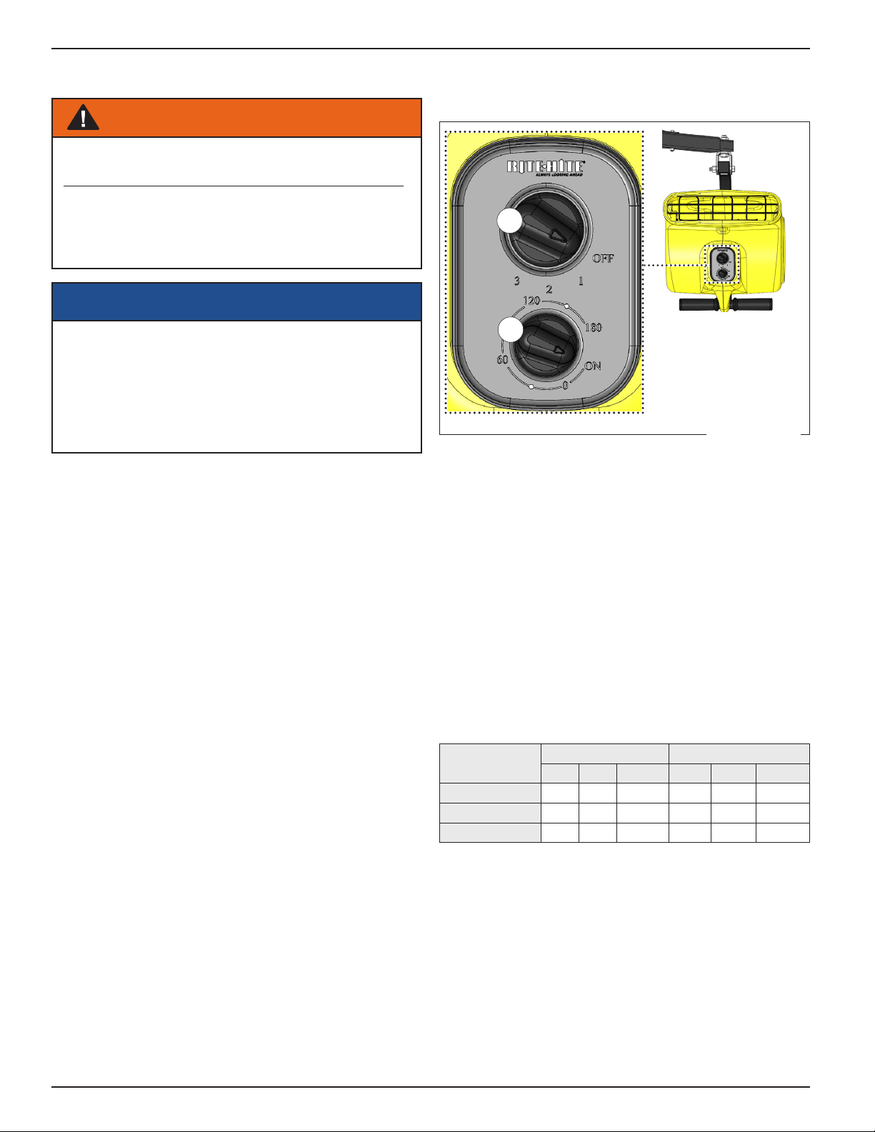
Fan Controls
A. Speed Control
Switch
B. Timer
Switch
A
B
The CoolMan 2800 fan is controlled with switches on the
front of the fan.
For normal operation:
• Rotate the timer switch (B) to ON.
• Rotate the speed control switch (A) to the desired setting.
For auto‑o operation:
• Rotate the timer switch (B) to desired time (1 to 180 min.).
• Rotate the speed control switch (A) to the desired setting.
The fan will not operate when:
• The timer swtich is in the 0 position
• The speed control switch is in the OFF position
Performance levels:
Switch Position 115V 60 Hz 230V 50 Hz
RPM CFM m3/min RPM CFM m3/min
1 1200 2000 57 1020 1900 54
2 1450 2600 74 1225 2200 62
3 1600 2800 80 1350 2400 68
Figure 7
CoolMan®2800 Trailer Fan with Rite-Lite™ LED Dock Light Installation/Service/Owner's Manual Rite-Hite®
10 Publication: AMEN00262 2019-12-09
Table des matières
Autres manuels RITE-HITE Ventilateur


