RFL SMX3 / 21 Page 8 of 22 Issue 1.4
User Manual 08 June 2009
7. Concatenation Port
The Concatenation Port provides optional direct connection to a co-located SMX3/21
that is serving another X.21 link. Unless interrupted by a particular V.24 port setting,
aggregate channel data passes between this port and the X.21 port. This port has
the same capacity as the X.21 Port. Signal timing is always transferred across the
Concatenation port when the port mode is set to ‘Enabled as Concatenation’.
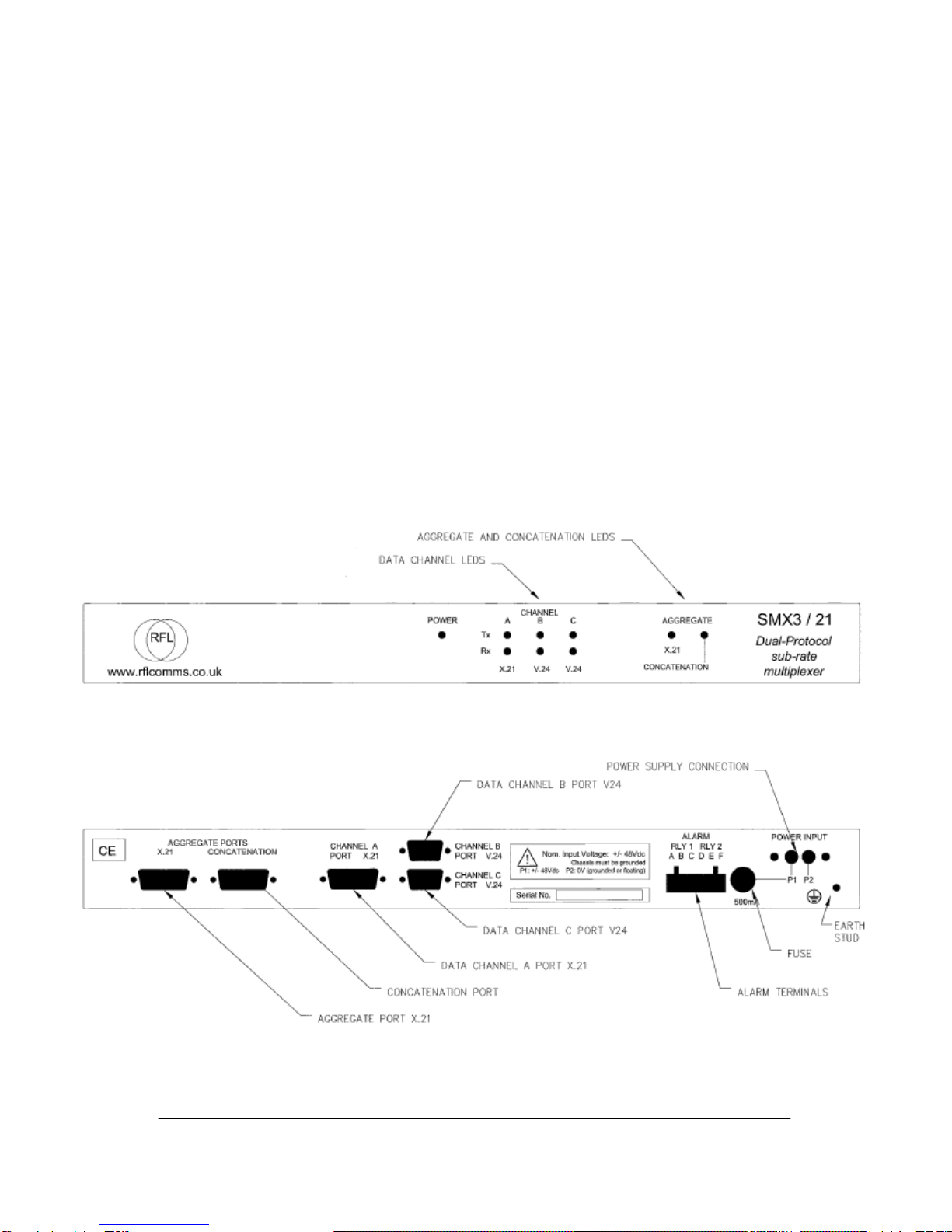
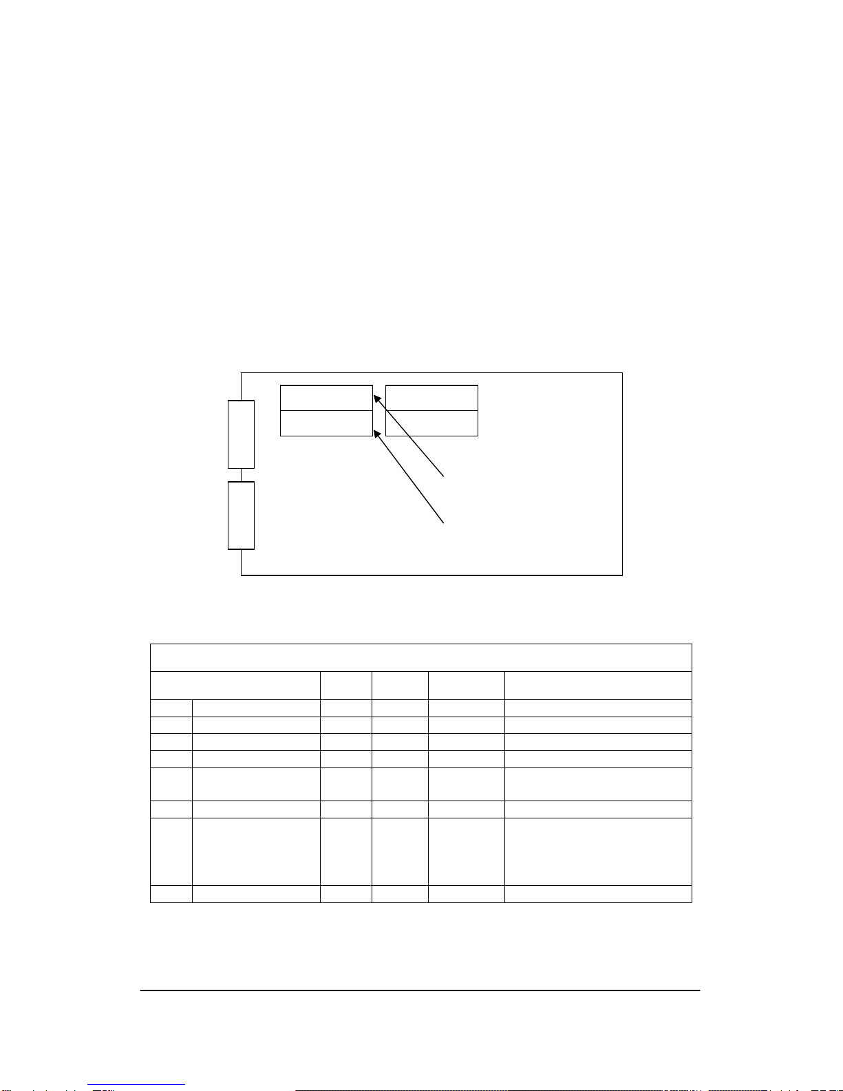
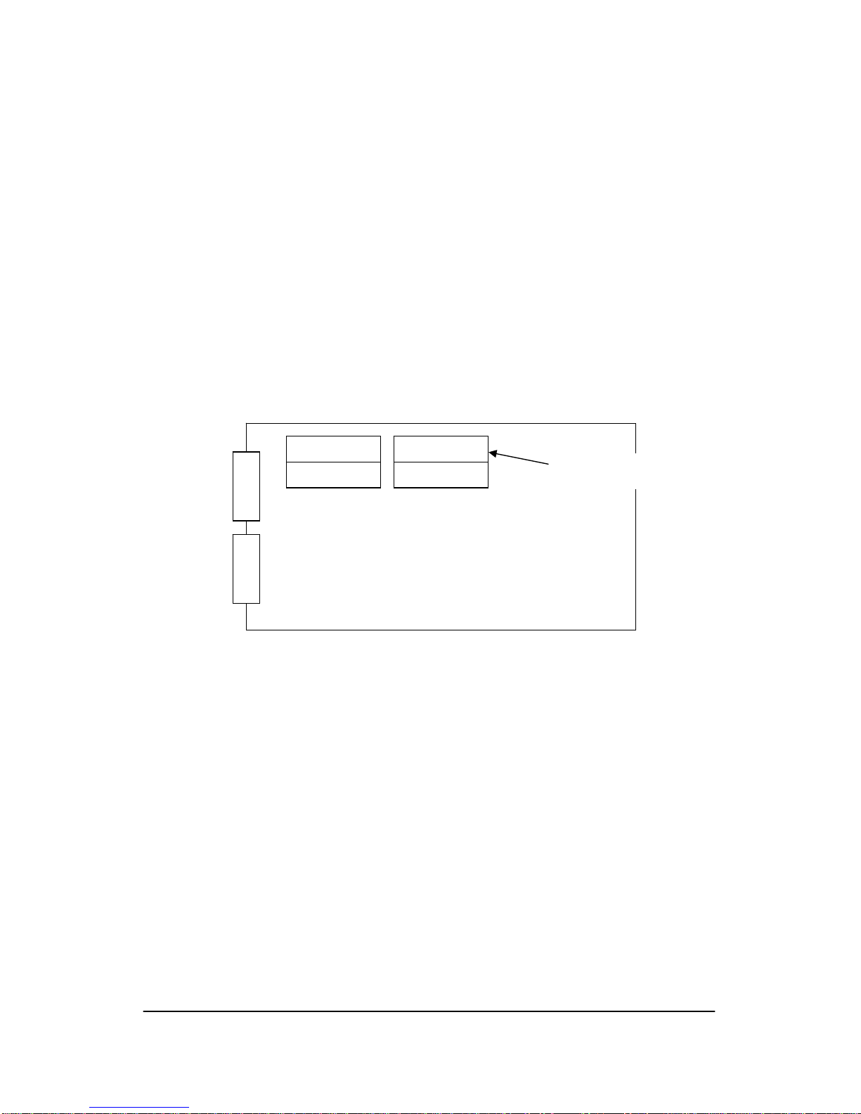
The Concatenation Port is a DB15 female connector; this is connected internally to a
header on the PCB using a ribbon cable. The Concatenation Port may be configured
as DTE or DCE by fitting the ribbon cable to the appropriate X.21 Port Header, and
by selecting settings on DIP switch 5. Note: DTE is the standard header location
used for Aggregate Concatenation i.e. direct connection to a co-located
SMX3/21.
Transceivers are specified to ± 15kV IEC1000-4-2 air discharge ESD protection and
port connections are additionally protected by Tranzorb type arrays.
Aggregate Concatenation
Aggregate Concatenation is the interconnection at aggregate level of two co-located
SMX3/21 units. For this function the Concatenation Port is configured as Enabled as
Concatenation mode, (i.e. DTE with Timing X enabled). The timing signal is derived
from the port and is transmitted on pins 7 and 14 (Xa and Xb).
In installations where the X.21 aggregate that is connected to each co-located unit
receives timing from the network master clock, the clock source for both units should
be configured as X.21 Port.
In installations where the X.21 aggregate that is connected to one or both co-located
units do not receive timing from the network, the source of the timing signal must be
determined and the clock source for each unit should be configured as X.21 Port,
Concat Port or Master as appropriate (refer to DIP Switch 6 settings).
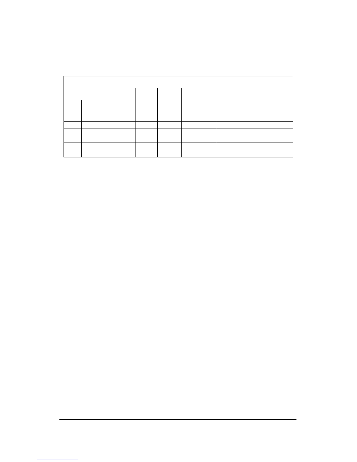
DIP switches provide configuration options, see section 10.
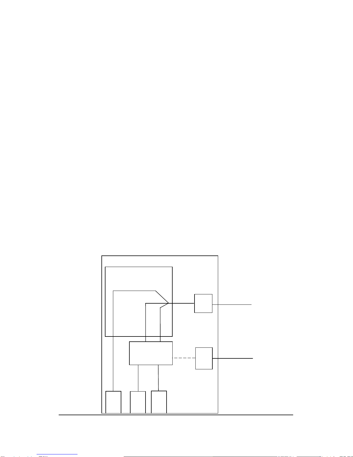
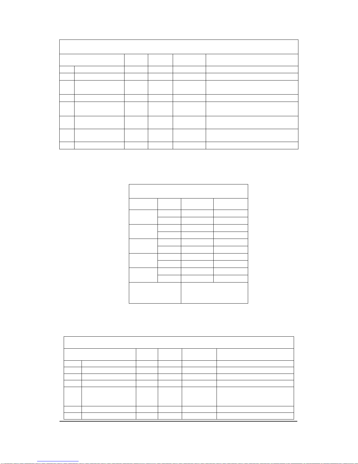
CONC. (DCE)
CONC. (DTE)
X.21V24
Headers connected
to X.21 Port Headers connected
to Concatenation