REVOV v2 Manuel utilisateur

REVOV Communication Unit v2
User Manual.
Introduction
The REVOV Communication Unit v2 (RCU v2) unit enables communication between
compatible lithium battery packs and CAN bus inverters. The RCU v2 features an
RS-485 port for connection to the battery’s Battery Management System (BMS) and
a CAN bus port for connection to the inverter. The RCU v2 allows the battery to
communicate directly with the inverter, allowing for the transfer of important
parameters such as current draw and battery voltage.
Rev. E (April 2021)
© REVOV 2021, under license
Page 1 of 16

Features
●Monitors various parameters of compatible batteries over RS-485.
●Transmits battery parameters over CAN bus to compatible inverters.
●Automatically sets up battery charging parameters based on the number of
connected batteries.
●Power is supplied directly from the battery
itself, reducing the number of cables used.
●Low power usage (50mA typical when
idle).
●Automatic self-shutdown when the battery
voltage falls too low.
●Rugged steel enclosure with convenient
mounting points.
Specifications
Parameter
Value
Input Voltage
8V to 60V1
Fuse Rating
User-replaceable, 800 mA fast-blow
Maximum BMS Count
12
Enclosure Size (l x w x h)
168 mm x 149 mm x 36 mm
Reverse Polarity Protection
Yes
Typical
Maximum
Current draw (24 V input)
100 mA
200 mA
Current draw (48 V input)
50 mA
100 mA
1Depending on the selected battery mode.
Rev. E (April 2021)
© REVOV 2021, under license
Page 2 of 16

Overview of operation
Battery parameters
The RCU v2 scans the parameters of connected BMSs, and reports these values to
the inverter. The following parameters are transmitted to the inverter over CAN
bus:
Parameter
Comment
Voltage [V]
Averaged between all connected BMSs.
Current [A]
Sum of all BMSs individual current values.
State of charge [%]
Averaged between all connected BMSs.
Temperature [°C]
The highest temperature reported by any BMS.
Device name
Fixed as “RCU v2.1”.
In addition, the RCU v2 determines appropriate charge and discharge settings
based on the type and number of connected BMSs. These charging and discharging
parameters are automatically communicated to the inverter.
Parameter
B100
R92
Max. charge current [A]
50 A per battery
100 A per battery
Max. discharge current [A]
100 A per battery
150 A per battery
Charge voltage [V]
55.5 V
Float voltage [V]
54.5 V
As an example, if the RCU v2 is connected to a bank that contains 9 of the B100
batteries, a maximum charge current of 450A and discharge of 900A will be
reported to the inverter.
Parameters not mentioned above are not reported to the inverter.
2Assuming the R9 battery is paired with a Tian Power BMS.
Rev. E (April 2021)
© REVOV 2021, under license
Page 3 of 16

Status indicator lights
The RCU v2 has built-in green, yellow and red LEDs on the front surface of the
enclosure. These are programmed to display the internal state of the unit:
Front LEDs
Status description
Green
Yellow
Red
Off
Off
Off
No power connected.
On
Off
On
Communication error.
On
On
Off
All good.
In addition, the RS-485 port and CAN bus port have LEDs to show the status of
communication on each port respectively:
RS-485 LEDs
Status description
Green
Yellow
Off
Off
No RS-485 communication.
Flashing
Flashing
RS-485 communication active.
CAN bus LEDs
Status description
Green
Yellow
Off
Off
No CAN bus communication.
Flashing
Flashing
CAN bus communication active.
Please note that after a status change (such as when plugging a communication
cable in or out) it may take several seconds for the LEDs to update.
Rev. E (April 2021)
© REVOV 2021, under license
Page 4 of 16

Under-voltage shutdown
When the input voltage provided to the RCU v2 (typically battery voltage) drops
past a certain point, the RCU v2 will turn off internal circuitry to avoid contributing
to further battery discharge. This protects the battery against potential
under-voltage damage by the RCU v2’s current draw.
The under-voltage shutdown level can be set to a specific battery voltage range
(i.e. 48 V mode or 24 V mode) by changing the position of a jumper (JP6) on the
circuit board. This should be done by authorised personnel only. The RCU v2 will
not function without a jumper present.
Selected mode
Turn-off voltage
Turn-on voltage
48 V mode (default)
< 32 V
> 34 V
24 V mode
< 17 V
> 18 V
Bypass mode
< 8 V
> 8 V
Bypass mode can be used to ignore battery voltage, thereby switching off the
under-voltage shutdown feature.
The RCU v2 is factory-defaulted to 48 V mode.
Rev. E (April 2021)
© REVOV 2021, under license
Page 5 of 16

Installation and configuration
General setup instructions
1. The RCU v2 is powered from the battery terminals using the provided power
cable. Connect the power cable to the battery terminals first, but do not yet
provide power to the RCU v2.
2. Plug the RS-485 communication cable into the RS-485 port of the RCU v2,
and then into BMS’s RS-485 port. Ensure that this cable’s pinout is correct.
3. Plug the CAN bus communication cable into the CAN bus port of the RCU v2,
and then into the CAN bus port of the inverter. If the inverter requires it,
ensure that CAN bus termination is applied (typically by inserting a
termination plug into an empty CAN bus port on the inverter).
4. Perform inverter-specific setup as required (refer to the relevant section for
instructions)
5. Provide power to the RCU v2 by plugging in the power cable.
Rev. E (April 2021)
© REVOV 2021, under license
Page 6 of 16

6. Wait 30 seconds for the RCU v2 to power up. On startup, the green and red
LEDs will illuminate. As soon as communication is established on both the
RS-485 and CAN bus ports, the red LED will switch off and the yellow LED
will illuminate. The green and yellow LEDs next to the RS-485 and CAN bus
ports will also flash alternately to signal communication.
7. Confirm that the inverter is receiving battery parameters. The RCU v2 is now
successfully set up and communicating! Refer to the Troubleshooting section
if any unexpected behaviour occurs.
8. When making any configuration changes (such as using a different cable, or
changing inverter settings), restart the RCU v2 by removing the power plug
for 10 seconds, then re-applying power.
Victron-specific setup instructions
1. Ensure that the correct CAN bus cable is made up. Refer to elsewhere in this
manual for the correct pinout.
2. Plug the CAN bus cable into a port labelled “VE.Can” on the Victron GX device
that is acting as the controller.
3. On the console of your GX device, under device list:
a. Navigate to “Settings”
b. Navigate to “Services”
c. Navigate to “VE.Can port”
d. Navigate to “CAN-bus profile”
e. Select “CAN-bus BMS (500 kbit/s)”
4. After RCU v2 power-up, the GX device will automatically detect the RCU v2
and parameters will be automatically passed to the inverter.
Rev. E (April 2021)
© REVOV 2021, under license
Page 7 of 16

Sunsynk-specific setup instructions
1. Ensure that the correct CAN bus cable is made up. Refer to elsewhere in this
manual for the correct pinout.
2. Plug the CAN bus cable into the port on the Sunsynk inverter that is labelled
“DSM_CAN”.
3. The Sunsynk inverter will not automatically detect the RCU v2 if it is not set
up for a lithium battery in CAN mode. To set the Sunsynk up in this way,
perform the following steps on the Sunsynk’s interface:
○While on the home screen, click on the “battery” icon (shown in the
left picture below).
○Make sure that the “Lithium” and “CAN” checkboxes are ticked (show
in the right figure below).
4. After the RCU v2 has been powered on:
○Operation can be confirmed by looking at the “Li BMS” icon (shown in
the left picture below).
○The Sunsynk will also automatically populate charging and discharging
parameters.
Rev. E (April 2021)
© REVOV 2021, under license
Page 8 of 16

GoodWe-specific setup instructions
1. Ensure that the correct CAN bus cable is made up. Refer to elsewhere in this
manual for the correct pinout.
2. The GoodWe inverter will not automatically detect the RCU v2 if it is not set
up for the correct lithium battery. To do this:
a. Open the GoodWe PV Master app on a smartphone, and connect to the
GoodWe inverter Wi-Fi access point.
■Default SSID: Solar-Wifi****
■Default password: 12345678
b. Once logged in, click “Basic Settings” and select the appropriate
country and working mode. There will be an installer’s code prompt.
Attempt to use “goodwe2010” as the installer’s code. If that doesn’t
work, it will be necessary to obtain the latest code from GoodWe.
c. From there, select “default lithium battery (100Ah)” as the battery
type. Complete the setup and return to the parameters tab.
3. Once the RCU v2 is powered, it will start to communicate with the GoodWe
inverter. This can take up to 30 seconds.
Rev. E (April 2021)
© REVOV 2021, under license
Page 9 of 16
SMA-specific setup instructions
1. Ensure that the correct CAN bus cable is made up. Refer to elsewhere in this
manual for the correct pinout.
2. Plug the CAN bus cable into the port and into the port labelled “ComSyncIn“
on the SMA inverter.
3. The SMA will not automatically detect the RCU v2 if it is not already set up
for the correct lithium battery. To do this, follow these steps on the Sunny
Remote Control device connected to the inverter:
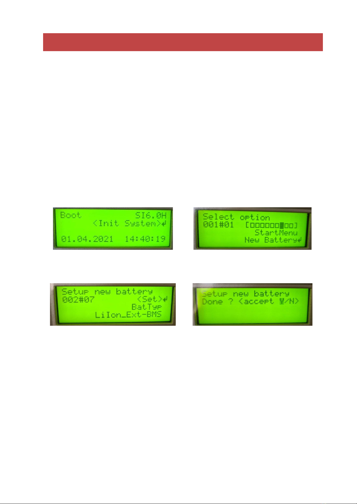
Step 1: Upon restart, place the SMA
into “Init System” mode.
Step 2: Scroll and select the “New
Battery” option.
Step 3: Setup the new battery type to
be “LiIon_Ext-BMS”
Step 4: Accept and save the options
and then start the inverter.
4. Once the RCU v2 is powered, the SMA inverter will accept the battery
parameters as communicated to it by the RCU v2.
Rev. E (April 2021)
© REVOV 2021, under license
Page 10 of 16
Table des matières


