FRONT PANEL CONTROLS (continued)
LIMITER FEEDBACK
Left to run freely, vacuum tubes are not linear and exhibit a considerable amount of harmonic
generation and other forms of distortion. For over half a century, negative feedback has been
engineered into circuits to “improve” the linearity of vacuum tubes when used in audio gain
stages. However, best readings on a meter don’t always equate to the ideal sound, whatever
that happens to be. By making LIMITER FEEDBACK an adjustable feature, harmonic content
and texture are put into the hands of the audio engineer and not the guy with the THD meter.
As an initial setting for the LIMITER FEEDBACK control, be sure the UNITY position is selected
(Channel 1 & Channel 2). In order to maintain correct gain structure for accurate IN/BYPASS
review, LIMITER FEEDBACK should be used in tandem with the OUTPUT LEVEL control.
Since both OUTPUT LEVEL and LIMITER FEEDBACK are step attenuated in 1dB increments
this is fairly easy to do.
LIMITER FEEDBACK - OPERATIONAL NOTE:
LIMITER FEEDBACK has a direct effect on the output level of the audio, which is why it is
done in calibrated 1dB increments on the L2M. Because of this, proper setting of make-up gain
is the combined settings for OUTPUT LEVEL and LIMITER FEEDBACK which should be set to
the inverse of the GR METER reading.
For example, a -5dB meter reading of PEAK REDUCTION would allow for a setting of +5dB on
the OUTPUT LEVEL and a 0dB setting on LIMITER FEEDBACK. In this example, you would
maintain UNITY and have the cleanest possible signal.
In the same example, a -5dB meter reading of PEAK REDUCTION would allow for a setting of
0dB on the OUTPUT LEVEL and a +5dB setting on LIMITER FEEDBACK. In this example, you
would maintain UNITY and add additional harmonics. Naturally, you could have +2dB on
OUTPUT LEVEL and +3dB on LIMITER FEEDBACK.
As an extreme example, -5dB of PEAK REDUCTION would allow for a setting of -5dB on the
OUTPUT LEVEL with a +10dB on LIMITER FEEDBACK. With this setting, you would main-
tain UNITY and provide maximum harmonic generation, which can bring added “life” and “in-
terest” to a dull sounding recording or be just the right texture for a lead vocal or guitar to stand
out. Maybe, maybe not, it’s up to you.
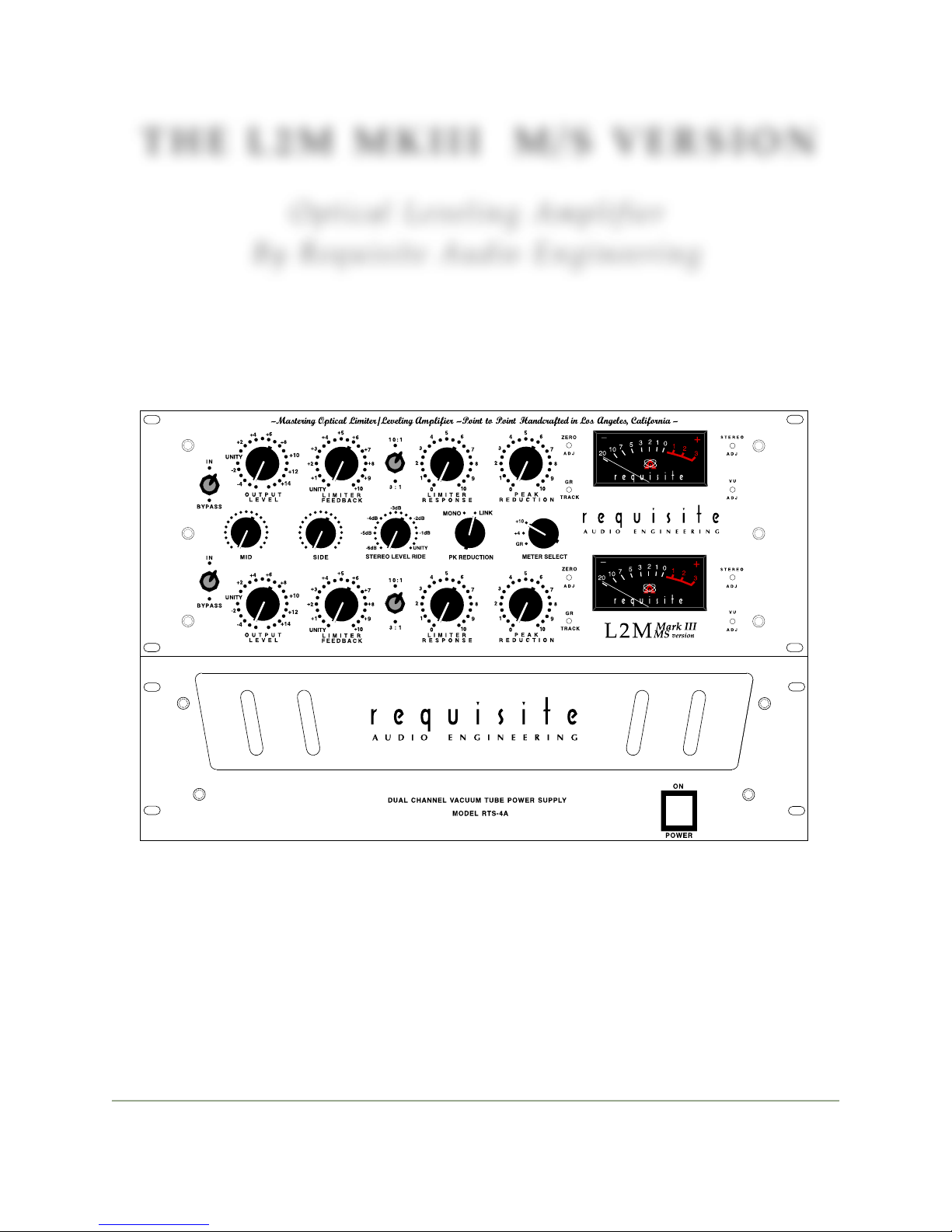
THE L2M MKIII M/S VERSION
Requisite Audio Engineering!L2M MkIII
5