Redline SMOKE PRO AIR COMPLETE 95-0051 Manuel utilisateur
Manufactured in California, USA*
REDLINE MODEL NO: 95-0051
OPERATION MANUAL
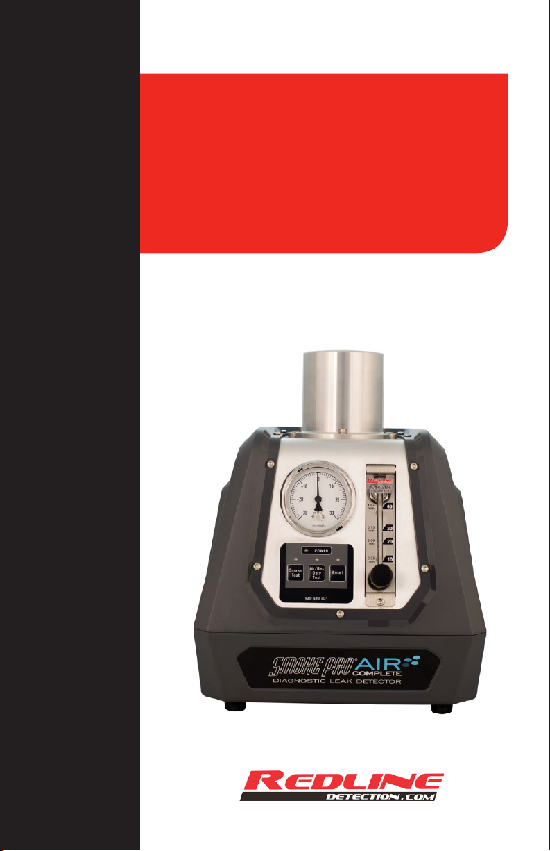
SMOKE PRO®AIR COMPLETE™
DIAGNOSTIC LEAK DETECTOR

CONGRATULATIONS
Thank you for purchasing the
Air Complete™Diagnostic Leak
Detector.
Your new Air Complete™contains
its own onboard micro compressor,
eliminating the need for air lines
and gas tanks. Whether a repair
job is across the service facility or
across the lot, Air Complete™
allows you to go where the work is.
Made by the team that brought
you the world’s best-selling
diagnostic leak detectors,
Air Complete™ will not only
help you to quickly locate and
repair leaks, it will help you to
find more repair jobs. Use
Air Complete™ to quickly test
every vehicle that comes into
your shop and see how it will
help you to work smarter and
make more money.
Portability. Performance. Profit.
Air Complete™ is the complete
diagnostic solution.
Zachary Parker
President
Redline Detection, LLC
CONTENTS
Specifications.............................. 1
Reference Guide......................... 2
Safety............................................. 3
Accessories.................................. 4
Set up............................................. 6
Testing for Leaks.......................... 7
How to Diagnose Leaks:
Intake System / Vacuum Leaks... 8
EVAP - Fuel Vapor Recovery
System Leaks.............................. 9
Exhaust System Leaks................ 10
Under DashBoard Leaks............ 10
Troubleshooting............................ 11
Maintenance................................. 12
Warranty ....................................... 13
L x W x H 8 in. x 10 in.x 12.5 in. (20 cm x 25 cm x 33 cm)
Weight 10.3 lbs. (4.5 kg)
Shipping Weight 18 lbs. (8 kg)
Power Supply 12 Volts DC
Power Consumption 8 amps
Output Pressure 0.5 PSI / 13.0 in. H20 / 0.032 BAR
Operating Temperature 30°F to 140°F (-1°C to 60°C)
Operating Humidity No Restrictions
Operating Altitude No Restrictions
Vapor Output Hose 10 ft. (3 m)
Power Supply Cables 20 ft. (6 m)
Operating Modes Vapor Test Cycle
Air Only Test Cycle
Pressure Supply Onboard Micro Air compressor
Micro-compressor Duty Cycle 100%
Housing Material High-Impact PC / ABS Polycarbonate
Vapor Chamber Material Billet Aluminum
Vapor Chamber Assembly Bolted
Vapor Chamber Warranty Lifetime
SPECIFICATIONS
1
Specifications.............................. 1
Reference Guide......................... 2
Safety............................................. 3
Accessories.................................. 4
Set up............................................. 6
Testing for Leaks.......................... 7
How to Diagnose Leaks:
Intake System / Vacuum Leaks... 8
EVAP - Fuel Vapor Recovery
System Leaks.............................. 9
Exhaust System Leaks................ 10
Under DashBoard Leaks............ 10
Troubleshooting............................ 11
Maintenance................................. 12
Warranty ....................................... 13
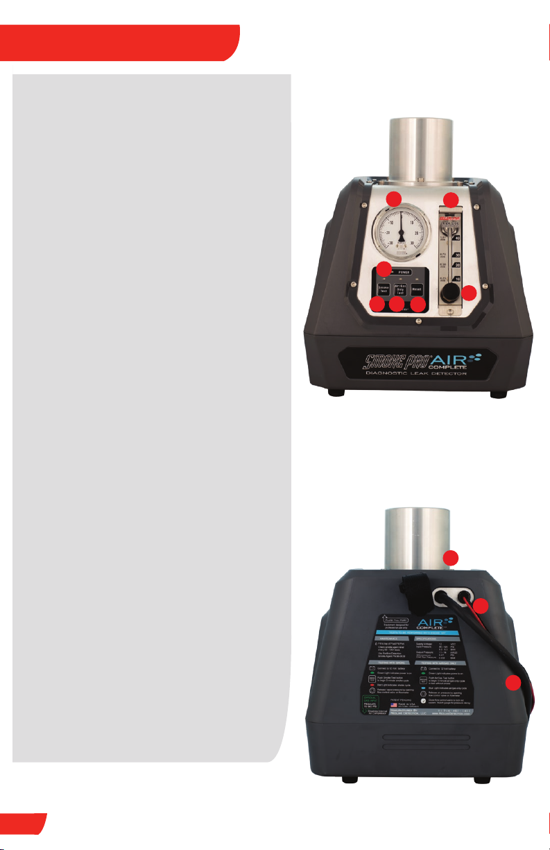
1. Compound Pressure Gauge
Indicates amount of pressure or vacuum
Allows for Decay / Leak Down test to
confirm repair is 100% complete
2. Flow Meter
Measures leak size as small as 0.010”
3. Flow Control Knob
Releases vapor / pressure into system by
opening the flow control valve
Close flow control valve to lock out
system for pressure decay testing
4. Power Indicator Light
Green light indicates adequate power
5. Smoke Test Button
Begins 5-minute vapor cycle
Red light indicates vapor cycle
Push again to stop testing
6. Air-Only Test Button
Begins 5-minute air-only cycle to test
without vapor
Blue light indicates onboard micro
compressor is generating air-only
7. Reset Button
Clears stored logic
8. Fluid Fill Port
Use Hex Key to remove Fluid Fill Plug
9. Battery Power Cables
Connects to 12-Volt DC battery(+)
and chassis ground(-)
10. Vapor Output Hose
REFERENCE GUIDE
2
12
3
4
567
8
FRONT VIEW
10
9
BACK VIEW

SAFETY
!
3
The procedures in this operation manual are intended to be basic guidelines for
users to practice using this diagnostic leak detector
This operation manual is not intended to be used in place of common sense:
• Use this equipment in the manner specified by the manufacturer
• Understand operating procedures
Follow all safety precautions
SAFETY PRECAUTIONS
• All diagnostic work should be performed with the engine off
• Do not leave a vehicle unattended while equipment is connected or operating
• Operates on a 12 Volt battery: Connect to battery (+) and chassis ground (-)
• Vapor Chamber can become host. Do not lift or carry by vapor chamber
• Do not perform tests near a source of spark of ignition
• When working with the fuel system, work in a well-ventilated area
• Always wear the appropriate safety protection
Wear OSHA standard eyewear and protective gloves when using this equipment
Always use a supplemental hood support or prop rod whenever hanging
unit under a hood
FRONT VIEW
BACK VIEW
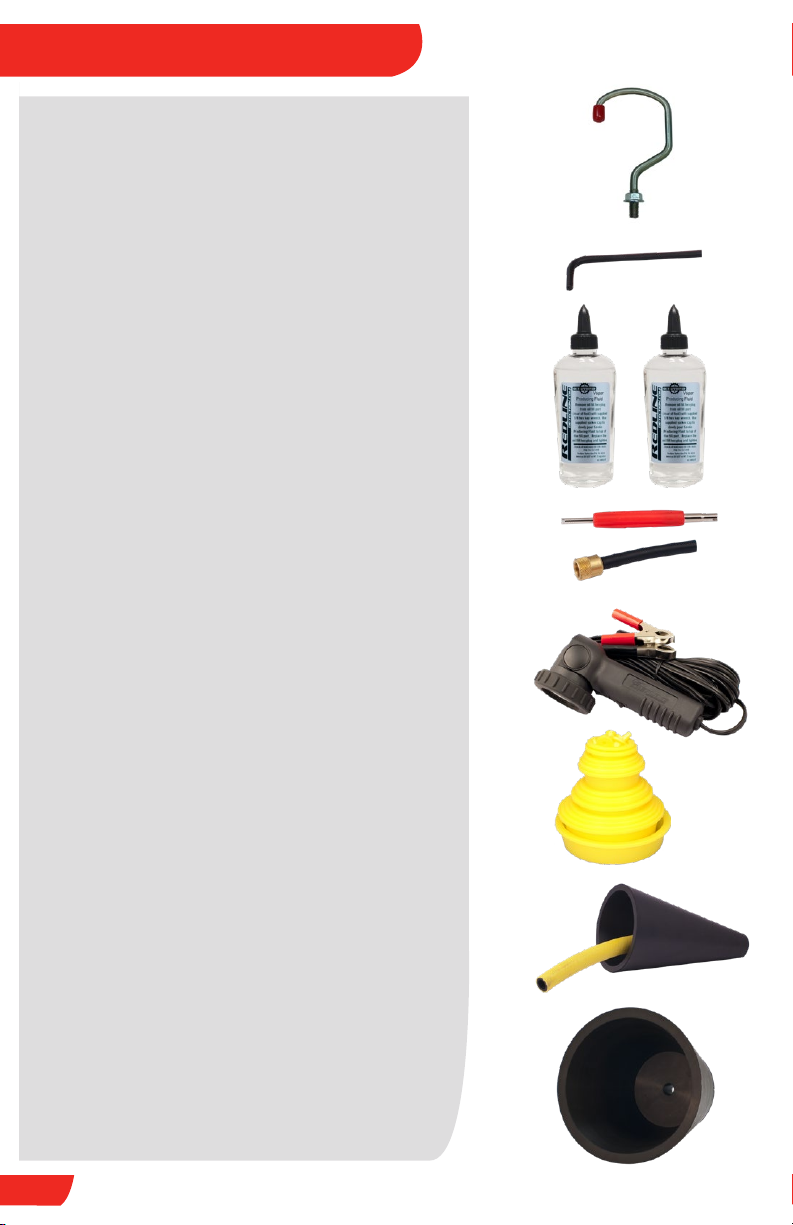
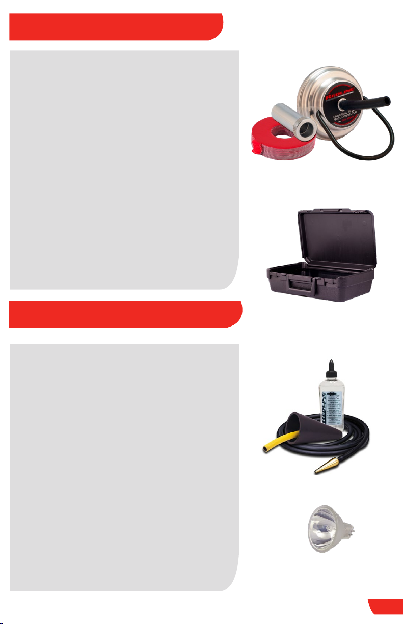
Handle / Hook [PN 96-0053]
To properly carry Air Complete and hang under
hood or chassis
Hex Key [PN 80-0009]
To remove / replace fluid fill plug
OEM-Approved Vapor Producing Fluid
[PN 96-0039]
Vapor Producing Fluid will perform over
1,000 typical tests (500+ per bottle)
IMPORTANT: Contains NO Dye / Contaminants
EVAP Service Tool Kit [PN 96-0003]
Schrader Valve Removal Tool
EVAP Service Port Adapter
Halogen Inspection Light [PN 96-0011]
Bright white beam finds even the tiniest
wisps of vapor under the hood or chassis
Cap Plug Kit [PN 96-0007]
Seals a variety of openings in order to
pressurize system for testing
Standard Cone Adapter [PN 96-0004]
For use to seal openings from 1 in. (2.5 cm) to
3.4 in (8.6 cm) to introduce vapor into exhaust
and induction systems
XL Cone Adapter [PN 96-0055]
For use to seal openings from 3.4 in. (8.6 cm)
to 5.25 in (13.3 cm) to introduce vapor into
exhaust and induction systems
ACCESSORIES INCLUDED
4
ACCESSORIES INCLUDED
ADDITIONAL ACCESSORIES
EasyEVAP™ [PN 95-0030]
This universal Fuel Filler Neck Connector
system fits 100% of vehicles to simplify
EVAP testing
Sealing Disks [PN 96-0017-12]
Creates an air-tight seal with any filler neck
CapAdapt™ Capless Adapter [PN 96-0054]
Opens throat of cap-less filler necks
Accessory Storage Case [PN 91-0011]
Extended Accessory Kit [PN 95-0005]
Standard Cone Adaptor for dual exhaust
Vapor Output Hose extension allows operator
to test 20 ft. (6.1 m) from unit
Additional OEM-Approved vapor producing
fluid for 500+ typical tests
Replacement Bulb [PN 20-0002]
MR-16 bulb, replacement for Inspection Light
5
HOOK UP
SET UP
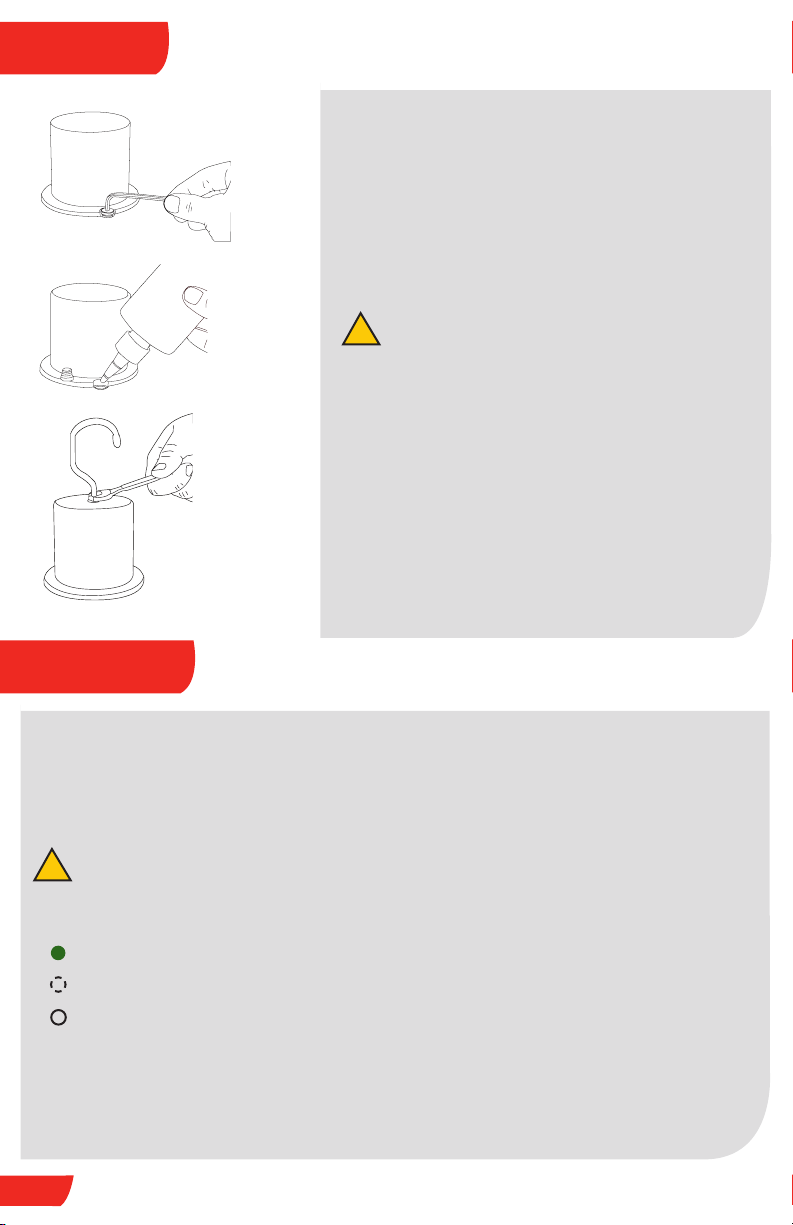
1. FILL / ADD VAPOR PRODUCING FLUID
Remove Fluid Fill Plug with hex key
Pour OEM-Approved Vapor Agent into Fluid Fill
Port until fluid level is near top of Fluid Fill Port
Replace Fluid Fill Plug
Do not overfill
Only takes 2 fl. oz. (60 ml) to refill when empty
2. INSTALL HANDLE-HOOK
Use a wrench to tighten jam nut
6
!
3. CONNECT TO POWER
This machine runs on a fully-charged 12-Volt battery
Connect red lead (+) to battery’s positive terminal
Connect black lead (-) to chassis ground
Do not connect to battery charger
POWER INDICATOR:
Green Light: Machine has adequate power
Flashing Green Light: Improper Power, Power is too high or too low
No Light: No Power, See Troubleshooting (Pg 11)
!

7
TESTING FOR LEAKS
4. TESTING WITH SMOKE
Push smoke test button to begin a 5-minute vapor cycle
VAPOR INDICATOR:
Red Light: Vapor is Generating
Flashing Red Light: See Troubleshooting (Pg 11)
No Light: No Vapor Generating
Turn Flow Control Knob counter-clockwise to release smoke / pressure
Flow Meter indicates flow and measures leak size
Use provided Halogen Inspection Light to locate leaks
Perform repair(s) as needed
5. TESTING WITH AIR-ONLY
Push Air-Only test button to begin a 5-minute vapor cycle
AIR-ONLY INDICATOR:
Blue Light: Machine has adequate power
Turn Flow Control Knob counter-clockwise to release pressure
Flow Meter indicates flow and measures leak
VERIFY REPAIRS
3. CONNECT TO POWER
This machine runs on a fully-charged 12-Volt battery
Connect red lead (+) to battery’s positive terminal
Connect black lead (-) to chassis ground
Do not connect to battery charger
POWER INDICATOR:
Green Light: Machine has adequate power
Flashing Green Light: Improper Power, Power is too high or too low
No Light: No Power, See Troubleshooting (Pg 11)
6. PERFORM DECAY / LEAK DOWN TEST
Pressurize the sealed system
Lock out system by turning Flow Control Knob clockwise to the fully closed position
OBSERVE PRESSURE GAUGE FOR DECAY:
Pressure Holds: No leaks, Repair is complete
Pressure Decreases:
Leak(s) exist, Repair Steps above until all repairs are complete
NOTE: Not all systems are designed to be 100% sealed

HOW TO DIAGNOSE INTAKE SYSTEM & VACUUM LEAKS
This procedure will locate leaks in vacuum lines as well as manifolds, EGR valves,
oil seals, gaskets, solenoids, o-rings, ducting, throttle shafts, diaphragms,
canisters, and more
For best results, test in a draft-free area
1. Remove the air filter housing from ducting
2. If the vehicle has a round inlet tube from the air filter, place the Cone Adapter
into the duct toward the engine
3. Put Vapor Supply Hose into Cone Adapter to introduce vapor into the
system
4. Use provided Halogen Inspection Light to locate leaks
ALTERNATIVE METHOD
1. Select an appropriate vacuum line to access the vacuum system
(i.e. a brake booster supply line before the check valve)
2. Seal all system openings
a. Air Intake must be sealed to prevent vapor from leaking back
through the intake
b. To seal the intake, use Cap Plugs, a latex glove, or plastic wrap around the filter
3. Put Vapor Output Hose into Cone Adapter to introduce vapor into the system
4. Use provided Halogen Inspection Light to locate leaks
8
Table des matières
Autres manuels Redline Capteur de sécurité


