Redarc BSEN500 Manuel utilisateur

Smart Battery
Monitor
BSEN500

CONTENTS
WARNINGS & SAFETY INSTRUCTIONS ����������������������������������� 3
PRODUCT OVERVIEW �������������������������������������������������������������� 4
Kit Contents ��������������������������������������������������������������������������������4
Wiring Diagram — Standalone Install�����������������������������������������������5
Wiring Diagram — R-Bus Install������������������������������������������������������5
SYSTEM PLANNING ���������������������������������������������������������������� 6
INSTALLATION—MOUNTING �������������������������������������������������� 8
Mounting Requirements ����������������������������������������������������������������8
Mounting Clearances ��������������������������������������������������������������������9
Mounting Instructions �����������������������������������������������������������������10
INSTALLATION — WIRING ������������������������������������������������������11
Lug Assembly ����������������������������������������������������������������������������11
Ground (GND) Cable Connection ��������������������������������������������������12
Battery Negative (B NEG) Cable Connection �����������������������������������14
R-Bus Cable Connection �������������������������������������������������������������15
Battery Sense Lead Connection����������������������������������������������������16
Strain-Relief and Cable Management ��������������������������������������������16
Care and Maintenance ����������������������������������������������������������������17
SYSTEM CONFIGURATION�����������������������������������������������������18
Get the RedVision®Congurator App ��������������������������������������������19
Edit a Conguration ��������������������������������������������������������������������20
OPERATION����������������������������������������������������������������������������21
Get the RedVision App ����������������������������������������������������������������21
TROUBLESHOOTING ��������������������������������������������������������������22
Faults ���������������������������������������������������������������������������������������22
TECHNICAL SPECIFICATIONS ������������������������������������������������24
WARRANTY ���������������������������������������������������������������������������27
For the latest version of this document and any available translations, visit the product page on
the REDARC website at www.redarcelectronics.com

WARNINGS & SAFETY INSTRUCTIONS
SAVE THESE INSTRUCTIONS — This manual contains
important safety instructions� Do not operate the system
unless you have read and understood this manual� REDARC
recommends that the products referenced in this manual be
installed by a suitably qualied person�
Disclaimer: REDARC accepts no liability for any injury, loss
or property damage which may occur from the improper or
unsafe installation or use of its products�
SAFETY MESSAGE CONVENTIONS
Safety messages in this manual include a signal word to
indicate the level of the hazard as follows:
WARNING: Indicates a potentially hazardous situation
which could result in death or serious injury to the operator
or to bystanders�
CAUTION: Indicates a potentially hazardous situation
which may result in moderate or minor injury to the operator
or to bystanders�
NOTICE: Indicates a situation that may cause equipment
damage�
WARNING
1. RISK OF EXPLOSIVE GASES: Working in the
vicinity of a Lead-Acid battery is dangerous�
Batteries generate explosive gases during normal
operation� For this reason, it is of utmost importance
that you follow the instructions when installing and
using the Battery Monitor�
2. Keep clear of naked ame, sparks and other sources of
ignition� This may cause the battery to explode�
CAUTION
1. Do NOT alter or disassemble the Battery Monitor
under any circumstances� All faulty units must be
returned to REDARC for repair� Incorrect handling or
reassembly may result in a risk of electric shock or
re and may void the unit warranty�
2. The Battery Monitor should not be used by persons
(including children) with reduced physical, sensory or
mental capabilities, or lack of experience and knowledge,
unless they are supervised or have been instructed on
how to use the appliance by a person responsible for
their safety� Children should be supervised to ensure that
they do not play with the Battery Monitor�
3. Only use the Battery Monitor with Standard Automotive
Lead Acid, Calcium Content, Gel, AGM, SLI, Deep Cycle
or Lithium Iron Phosphate type batteries�
4. Cable sizes are specied by various codes and standards
which depend on the type of vehicle the battery is installed
in� Selecting the wrong cable size could result in harm to
the installer or user and/or damage to the Battery Monitor
or other equipment installed in the system� The installer is
responsible for ensuring that the correct cable sizes are
used when installing this Battery Monitor�
5. If an undersized Battery Negative cable is used, frequent
device over temperature faults may occur�
6. Wiring must be installed in protected areas away from
heat sources and sharp objects� Cables must not be
routed over or through moving parts of the vehicle�
Additional protection such as conduit may be required,
especially if routing cables through the engine bay�
PERSONAL SAFETY PRECAUTIONS: To assist with the safe
operation and use of the Battery Monitor when connected to
the battery:
a. HOT SURFACE: High amperage loads connected
to the Battery Monitor can cause the terminal/metal
components to become extremely hot� To avoid burns,
do not touch the hot parts without suitable personal
protective equipment�
b. Wear complete eye protection and clothing protection�
Avoid touching eyes while working near a battery�
c. If battery acid contacts your skin or clothing, remove
the affected clothing and wash the affected area of your
skin immediately with soap and water� If battery acid
enters your eye, immediately ood the eye with running
cold water for at least 10 minutes and seek medical
assistance immediately�
NOTICE
Keep the Battery Monitor away from major heat sources,
high voltages, and avoid exposure to sunlight for long
periods of time�
DO NOT install the Battery Monitor in the engine bay,
this Product is not designed to operate in engine bay
environments�
The installer is responsible for applying the correct torque
to the Terminal Bolts� Over-torquing bolts may damage
the terminals�
Do not bottom-out thread when fastening Terminal
Bolts into the terminal, this may cause a poor electrical
connection (see 'Correct Lug Fitment' (page14))�
Do not t the Battery Sense Lead between the auxiliary
battery and lugs carrying high currents�

4 | Product Overview
PRODUCT OVERVIEW
The Battery Monitor provides critical system
information including battery voltage, current,
State of Charge (SoC) and temperature
information of the connected battery via the
RedVision®App�
The Battery Monitor can be combined with
REDARC R-Bus compatible products, including
the Manager with the RedVision®Display�
The Battery Monitor can also be used
independently to monitor and provide
information of the connected battery via the
RedVision®App�
Get the Free
Configurator App
Configure the settings of your
Battery Monitor using your
smartphone via Bluetooth®�
Get the Free
RedVision®App
Monitor and control your
RedVision®System using your
smartphone via Bluetooth®�
The RedVision®App and the Congurator App and their interactions
with the Battery Monitor have not been tested on all smartphone
models� Visit the application pages within your App store to view
compatibility details�
KIT CONTENTS
Smart Battery
Monitor Unit
Battery Sense Lead
1 m (3.3')
R-Bus (RJ45) Cable
2 m (6.6')
Alternative Terminal Bolt
M10 ×20 mm
Control
Button
Status LED
Mounting
Holes (×2)
R-Bus Network
Socket
Battery Sense
Lead Socket
Standard Terminal Bolt (×2)
M10 ×16 mm

Product Overview | 5
WIRING DIAGRAM — STANDALONE INSTALL
to Auxiliary
Battery
Positive (+)
Terminal
Auxiliary
Battery
to Vehicle
Common Ground
(not supplied)
RedVision® App
Ground
Terminal
Battery Negative
Terminal
to Auxiliary Battery
Negative (–) Terminal
(not supplied)
Battery
Sense Lead
Battery Sense
Lead Interface
WIRING DIAGRAM — R-BUS INSTALL
Ground
Terminal
to Auxiliary
Battery
Positive (+)
Terminal
R-Bus Cable
Battery
Sense Lead
to Auxiliary Battery
Negative (–
) Terminal
(not supplied)
to R-Bus
Interface
Auxiliary
Battery
Battery Negative
Terminal
to Vehicle
Common Ground
(not supplied)
REDARC Manager
(BMS1230S3)
RedVision® App
R-Bus and Battery
Sense Lead Interfaces
Refer to the Instruction Manual supplied with your Manager for detailed mounting and installation instructions�
This wiring diagram shows a common/typical system conguration� If unsure, contact REDARC Technical Support for advice
on your individual system requirements� See page15 for more information on R-Bus system wiring.

6 | System Planning
SYSTEM PLANNING
WHAT YOU WILL NEED
To mount, install and manage cabling of the Battery Monitor, the following common automotive electrical tools
and consumables may be required:
Heatshrink
Suitable cable lug
crimping tool
Cable cutters
Screwdriver / power drill
Spanner or Socket to suit M10
Cable ties
P-Clips
COMMON GROUND
Before planning wiring, consider that the Ground (GND ) connection and all components in your setup must
share a common electrical ground for correct system operation� This is typically achieved by connecting all
grounds to the vehicle body�
NOTE: Your auxiliary battery's negative connection is made via the Battery Negative (B NEG –) terminal on
the Battery Monitor�
LUG REQUIREMENTS
The Ground (GND ) and Battery Negative (B NEG –) terminals have M10 screw threads� Select lugs with a
10 mm (7/16") stud hole and a cable barrel that suits the required cable gauge�
The Ground (GND ) terminal is capable of connecting multiple loads, for important lug requirements and
instructions see 'Connecting multiple loads' (page12)�
NOTE: If installing the lugs to the Battery Monitor terminals facing downwards, select a lug where the lug
tongue is long enough to cover the shunt surface� This is to ensure the lug cable barrel does not hit against
the shunt� See 'Strain-Relief and Cable Management' (page16) for more information�
M10 Thread M10 Thread
20 mm
(0.8")
≤ 20 mm
(0.8") Ø10 mm
7/16"

System Planning | 7
CABLE REQUIREMENTS
CAUTION:
Cable sizes are specied by various codes and standards which depend on the type of vehicle the
battery is installed in� Selecting the wrong cable size could result in harm to the installer or user and / or
damage the Battery Monitor or other equipment installed in the system� The installer is responsible for
ensuring that the correct cable sizes are used when installing the Battery Monitor�
If an undersized Battery Negative cable is used, frequent device over temperature faults may occur�
Wiring must be installed in protected areas away from heat sources and sharp objects� Cables must
not be routed over or through moving parts of the vehicle� Additional protection such as conduit may
be required, especially if routing cables through the engine bay�
Appropriate cables are required for the Ground (GND ) and Battery Negative (B NEG –) terminals�
BATTERY NEGATIVE CABLE
The Battery Negative cable should be no longer than 1 m (3'3") to minimise the voltage drop between the
Battery Monitor and auxiliary battery� Refer to the table below to determine a suitable cable gauge for this
connection based on the current your system setup has�
IMPORTANT: The following table should be used as a reference only, considerations when selecting an
appropriate cable for your installation include:
Cable length
Peak current draw
Time spent at high current
Environment ambient temperature
System Current 100 A 200 A 300 A 400 A 500 A
Maximum Cable Length 1 m (3'3")
Recommended Cable
Cross Section 35 mm² 70 mm² 95 mm² 120 mm² 150 mm²
Closest Equivalent
AWG/BAE/B&S 23/0 4/0 250 kcmil 300 kcmil

8 | Installation—Mounting
INSTALLATION—MOUNTING
MOUNTING REQUIREMENTS
NOTICE: DO NOT install the Battery
Monitor in the engine bay, this Product
is not designed to operate in engine bay
environments�
START
BATTERY
The Battery Monitor is designed for installation within the vehicles cabin or in a similarly protected
environment such as in a ute canopy, caravan or battery box�
Mount in a location that is dry and is not prone to high humidity� Liquid or vapour entering the Battery
Monitor can cause irreparable damage�
Mount in a location that will avoid using excessive cable length�
Test that the Battery Sense Lead will comfortably reach between the Battery Monitor and auxiliary battery
before installation (1m (3'3") of cable length)�
Test that the R-Bus cable will comfortably reach between the Battery Monitor and the R-Bus input on a
compatible REDARC product before installation (2 m (6'6") of cable length)�
DO NOT mount with the RBUS and BPOS( +) sockets facing upwards, to prevent condensation/liquids
running into the Battery Monitor� The Battery Monitor can be mounted in any other orientation�
Mount the Battery Monitor permanently to a xed surface that has adequate strength to support it when all
connections and wiring are in-place� DO NOT mount on any moveable parts�
The mounting surface must be at and safe to drill through—check the reverse side before drilling�
1mm (0.04")
Clearance

Installation—Mounting | 9
MOUNTING CLEARANCES
MOUNTING INTERFERENCES
Ensure the main housing of the Battery Monitor is clear from any protrusions (1 mm (0�04") clearance)�
1mm (0.04")
Clearance
MOUNTING IN AN ENCLOSED SPACE
HOT SURFACE: High amperage loads connected to the Battery Monitor can cause the terminal/metal
components to become extremely hot� For this reason, the installer is responsible to leave at least 30 mm
(1.2") of clearance on all sides and above the Battery Monitor to allow for air-ow�
Leave at least 100 mm (4") of clearance around the RBUS and BPOS ( +) sockets to allow for R-Bus
cable routing� This clearance also provides room for strain-relief and cable management once wiring is
complete� See 'Strain-Relief and Cable Management' (page16) for more information�
Mount in a location where the Control Button and Status LED are visible and accessible�
If installing the Battery Monitor in an enclosed space, make sure there is adequate venting� Two vents
should ideally be positioned at the top and bottom of the enclosure for cross-ow of air�
Vent
Vent
Enclosed
space
30 mm (1.2")
Clearance
Air cross-ow
Air cross-ow
Control Button
and Status LED
are visible
100 mm (4") Clearance
around RBUS and
BPOS sockets

10 | Installation—Mounting
MOUNTING INSTRUCTIONS
MOUNTING HARDWARE
When mounting the Battery Monitor, both
Mounting Holes must be used�
Ensure the selected fasteners are suitable for the
mounting surface and there is clearance-t through
the Mounting Holes on the Battery Monitor�
Ø 6.5 mm
(1/4")
8 mm
5/16"
Fasteners are
not supplied
Two fasteners are required for mounting the
Battery Monitor� REDARC recommend using
M6 (1/4") to M4 (8#) fasteners with washers�
If using countersunk fasteners, apply
countersunk washers to avoid damaging the
Mounting Holes�
Do not mount the Battery Monitor using
adhesives or adhesive tape.
Ø 6.5 mm
(1/4")
8 mm
5/16"
Fasteners are
not supplied
MOUNTING STEPS
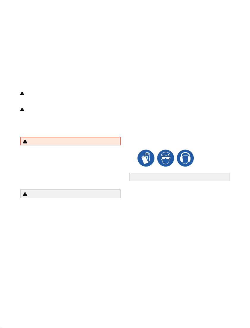
WARNING: Use suitable Personal Protective Equipment (PPE) when operating
power tools�
1. Conrm clearances around the Battery Monitor are adequate�
2. If clearance/pilot holes need to be drilled, place the Battery Monitor in its nal position and mark the
centre of each Mounting Hole�
3. Remove the Battery Monitor and drill the holes�
4. Fasten the Battery Monitor in place,
applying a washer in between the
fastener and the Mounting Hole�
Table des matières
Autres manuels Redarc Moniteur