Rebel AL6061 Manuel utilisateur

User Manual

·1·
About This Manual
This manual contains details of the product, and information on its operation and maintenance and other helpful tips for owners. Read it carefully and
familiarize yourself with the Rebel before using it to ensure safe use and prevent tragic accidents. Be sure to retain this manual as your convenient
information source.
This manual contains many Warnings and Cautions concerning the safe operation and consequences if safe setup, operation
and maintenance are not performed. All information in this manual should be carefully reviewed and if you have any
questions you should contact us immediately. The notes, warnings and cautions contained within the manual and marked by
this triangular Caution Symbol should also be given special care. Users should also pay special attention to information
marked in this manual beginning with NOTICE.
Because it is impossible to anticipate every situation or condition which can occur while riding, this manual makes no representations about
the safe use of bicycles under all conditions. There are risks associated with the use of any bicycle which cannot be predicted or avoided, and which are
the sole responsibility of the rider. You should keep this manual, along with any other documents that were included with your bicycle, for future
reference, however all content in this manual is subject to change or withdrawal without notice. Visit www.alteregobikes.com to download the latest
version. Alter Ego Electric Bikes makes every effort to ensure accuracy of its documentation and assumes no responsibility of liability if any errors or
inaccuracies appear within. Assembly and first adjustment of your Rebel requires special tools and skills and it is recommended that this should be
done by a trained bicycle mechanic if possible.
!

·2·
Product Specification
48v 17.5Ah Samsung Lithium Battery
Front Suspension & Hydraulic Lockout
750W High Speed Brushless Geared Motor
20” * 21” AL6061 M Model
KDS-KD51C+USB LCD Display
Hydraulic Disc 180mm
Shimano-Altus-7 Speed
Standard 3.0A Smart Charger
32 KPH
Shimano 7 Speed
80KM
Velo
Intelligent 5 Level Pedal Assist
Shimano-Tourney-ysp
Thumb Throttle
Kenda 20” x 4”
6~7 Hours
92 Ibs
5.2” ~ 6.4”
330 Ibs

·3·
On/Off Switch
LCD Display
Shimano Shifter
Brake
Handle LED Light Switch
Throttle
Saddle
Frame
Battery
LED Rear Light
Rear Shock Absorption
LED Head Light
Front Fork
Motor
Tire
Rear Derailleur
Controller Pedal
Front Brake

·4·
NOTICE: Before every ride it is important to carry out the following safety checks.
Maximum Load Capactiy
330 LBS
Wheelbase
43.7 inch
Seat Height Total Length
32 INCH
69 inch
Tires
20 X 4
Handlebar Reach
24 inch
Motor
750W
Safety Checklist

·5·
Brakes
o Ensure front and rear brakes work properly.
o Ensure brake pads are not over worn and are correctly positioned in relation to the rims.
o Ensure brake control cables are lubricated, correctly adjusted and display no obvious wear.
o Ensure brake control levers are lubricated and tightly secured to the handlebars.
Wheels and Tires
o Ensure tires are inflated to within the recommended limits displayed on the tire sidewalls.
o Ensure ties have tread and have no BULGES OR EXCESSIVE WEAR.
o Ensure rims run true and have no obvious wobbles or kinks.
o Ensure all wheel spokes are tight and not broken.
Steering
o Ensure handlebar and stem are correctly adjusted and tightened, and allow proper steering.
o Ensure the handlebar is set correctly in relation to the forks and the direction of travel.
Chain
o Ensure the chain is oiled, clean and runs smoothly.
o Extra care is required in wet or dusty conditions.
Cranks and Pedals
o Ensure pedals are securely tightened to the cranks.
o Ensure the cranks are securely tightened and are not bent.
Derailleurs
o Check that the derailleur(s) are adjusted and functioning properly.
o Ensure shift and brake levers are attached to the handlebar securely.
o Ensure all brake and shift cables are properly lubricated.
Motor Drive Assembly and Throttle
o Ensure hub motor is spinning smoothly and the motor bearings are in good working order.
o Ensure all power cables running to hub motor are secured and undamaged.
o Make sure the hub motor axle bolts are secured and all torque arms and torque washers are
in place.
Battery Pack
o Ensure battery is charged before use.
o Ensure there is no damage to battery pack.
o Lock battery to frame and check to see that it is secured.

·6·
NOTICE: The following assembly steps are only a general guide to assist in the assembly of your Rebel Bike and is not a
complete or comprehensive manual of all aspects of assembly, maintenance and repair. We recommend you consult a certified
bicycle mechanic to assist in the assembly, repair and maintenance of your bicycle.
Assembly Instructions
Step 1 : Install the handle bars. Remove the four screws from the stem, ensuring the linear markings on the handlebars are centered and
handlebars are adjusted to the comfortable position. Finally, tighten the screws with the assembly tool.
Step 2 : Install the headlight. Use a socket wrench to hold the nut and loosen the screw with a screwdriver and remove the screw. Install the
screw pass through headlight and the bracket and adjust the headlight properly for riding conditions.
Step 3 : Remove the plastic guard from the front fork being sure not use the brake levers until the wheel is installed.
Install the front wheel and make the axle go through the centre of the wheel.
Tighten the nut on each side with the wrench included.
Install the plastic cap on each side of the axle.
Remember to verify all items are tight and torqued properly after your first couple of rides.
Step 4 : Use a bike pump with a press gauge to Inflate tires to desired PSI. The recommended pressure for this mode is 20 PSI (1.379 Bar). Do
not overinflate or underinflate tires.

·7·
NOTICE: Ensure all hardware is tightened properly and all safety checks in the following sections are performed before first use.
Contact us if you have any questions regarding the assembly of your bike. If you are not able to ensure all the assembly steps in
the assembly instructions are performed properly, please consult a certified local bicycle service provider for assistance in
addition to contacting us for help.
: Install the pedals. The left and right pedals are marked on both ends. First, install the right pedal by tightening the pedal in clockwise
direction. The left pedal is tightened by turning the pedal in counterclockwise direction. Both pedals should be tightened to 35 Newton
meters by using a torque wrench.
: Install the optional rear rack. Align the holes in the rear rack with the holes in the frame and tighten with screws.
: Check the battery pack is locked into the frame of the Rebel . When you want to take off the battery, insert the key and turn
to release the battery pack. The battery pack can be removed and charged separately. This is the charging port. Align the battery pack to
the battery holder carefully and push until when you hear it click into the place.

·8·
Recommended Torque Values
Hardware Location
Torque Required (Nm)
Handlebar
18-20
Stem
18-20
Saddle
18-20
Front Wheel (For Bikes with Bolt on Front Wheel)
16-25
Rear Wheel
35-40
Bottom Bracket Parts
35-55
Pedals
35
Disk Mounting Bolts
6
Disk Caliper Mount
10
Crank Bolts
40
Rear Derailleur Cable Pinch
6
Front Derailleur Clamp
7
· 9 ·
Start-Up Procedure
After the bike has been properly assembled following the unboxing video and all components are secured correctly, you may now proceed to
start up the vehicle and select the power level following the next steps.
1. Hold down the centre mode button on the display remote for 2 seconds then release, the display should turn on.
2. Select your desired level of pedal assistance between level 0 through 5 using the up and down arrows on the display remote. Level 1
corresponds to the lowest level of pedal assistance, and level 5 corresponds to the highest level of pedal assistance. Level 0 indicates
pedal assistance will be inactive.
3. Toturn on the headlight once the LCD display are on, hold down the top and middle button located on the left side of the handlebars for
2-3 seconds.
4. With the proper safety gear and rider knowledge and understanding you may now proceed to operate your CHALLENGER Bike. You can
begin by pedaling the bike in the appropriate drivetrain gear with or without pedal assistance. You may also use the throttle to
accelerate and maintain your desired speed.
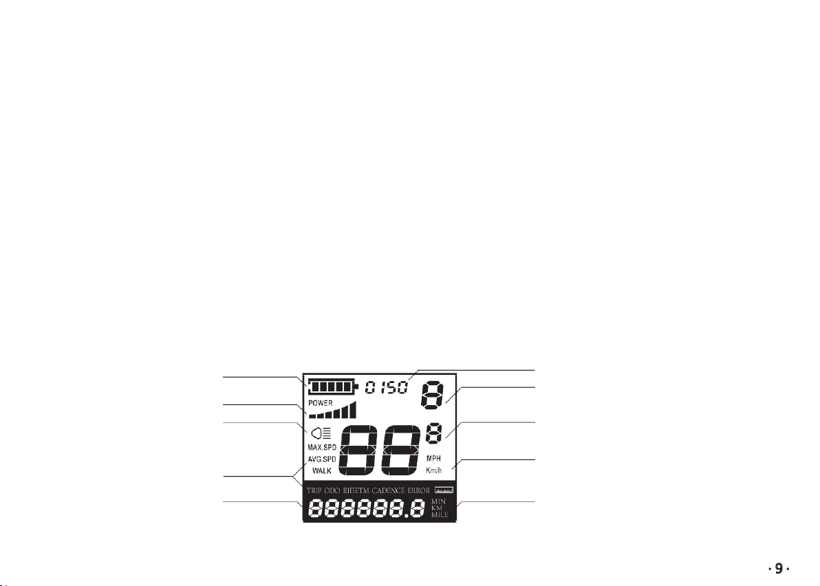
Display Features
The image shows the various features and information displayed on the Display.
Battery Indicator Power Output Indication
Push-assistance Level Indication Area
Power Indicator
The Lighting Indicator
Function List
Text Indication
Speed Indication
Speed Unit
Range / Time Unit
Table des matières


