RDZ EASY CLIMA Manuel utilisateur

Regulation
EASY CLIMA
USER MANUAL
9120206.03
05/2016
bit.ly/rdzwebsite
1.6
VERSION


3
SAFETY WARNINGS
Read this manual carefully before installation and/or use of
the equipment and keep it in an accessible place.
The Manufacturer’s Technical Dept. is available at the
numbers indicated on the back cover of this manual, for
consultancy or particular technical requests.
• CAUTION
Installation and maintenance must only be performed by
qualified staff; if this is not the case the warranty will
become null and void
• Only use original spare parts: failure to comply with this
norm can make the warranty null and void.
WARNINGS
DISPOSAL
In accordance with the provisions of the following
European directives 2011/65/EU, 2012/19/EU and
2003/108/EC, regarding reducing the use of
hazardous substances in electrical and electronic
equipment, in addition to waste disposal.
The symbol of the crossed-out wheely bin as shown on the
product indicates that at the end of its useful life it must be
disposed of separately from other waste.
The user must therefore dispose of the above equipment at the
end of its useful life at an appropriate centre for the collection
of electronic and electro-technical waste, or return it to the
dealer when purchasing a similar new device in terms of one
to one. Proper waste collection leading to the subsequent
recycling, treatment and environmentally friendly disposal of
the equipment helps to avoid possible negative eects on the
environment and on health and promotes the recycling of the
materials of which the equipment is made up.
Illegal disposal of the product by the user will lead to the
application of penalties prescribed by current legislation in
force.
4
INDEX
Num Description Page
WARNINGS 3
SAFETY WARNINGS 3
DISPOSAL 3
1 DESCRIPTION 5
GENERAL DESCRIPTION 5
DESCRIPTION OF DISPLAY 5
DESCRIPTION OF KEYS 7
2 SETTINGS 7
DATE AND TIME 7
USER SET-POINT 8
MAIN VALUES SHOWN ON THE DISPLAY 9
3 TIME BAND MANAGEMENT 10
EVENTS 10
PROFILES 10
PARAMETERS 10
ENABLING 12
PRIORITY 12
BLACK OUT 12
EXAMPLE OF TIME BANDS PROGRAMMING 13
4 EASY CLIMA CONTROLLER 16
DESCRIPTION 16
DESCRIPTION OF KEYS 16
DESCRIPTION OF SYMBOLS AND ICONS 16
DESCRIPTION OF DISPLAY 17
SET-POINT MODIFICATION 17
TIME BAND MANAGEMENT 17
5 DIAGNOSTICS 18
5
1DESCRIPTION
N.B. Easy Clima Controller can be coupled to hydraulic kits that
manage Low Temperature and/or High Temperature
systems such as:
Easy Clima Kit, LT only.
MTR Easy Clima both LT and HT.
The manual refers to the complete conguration for HT/LT
management
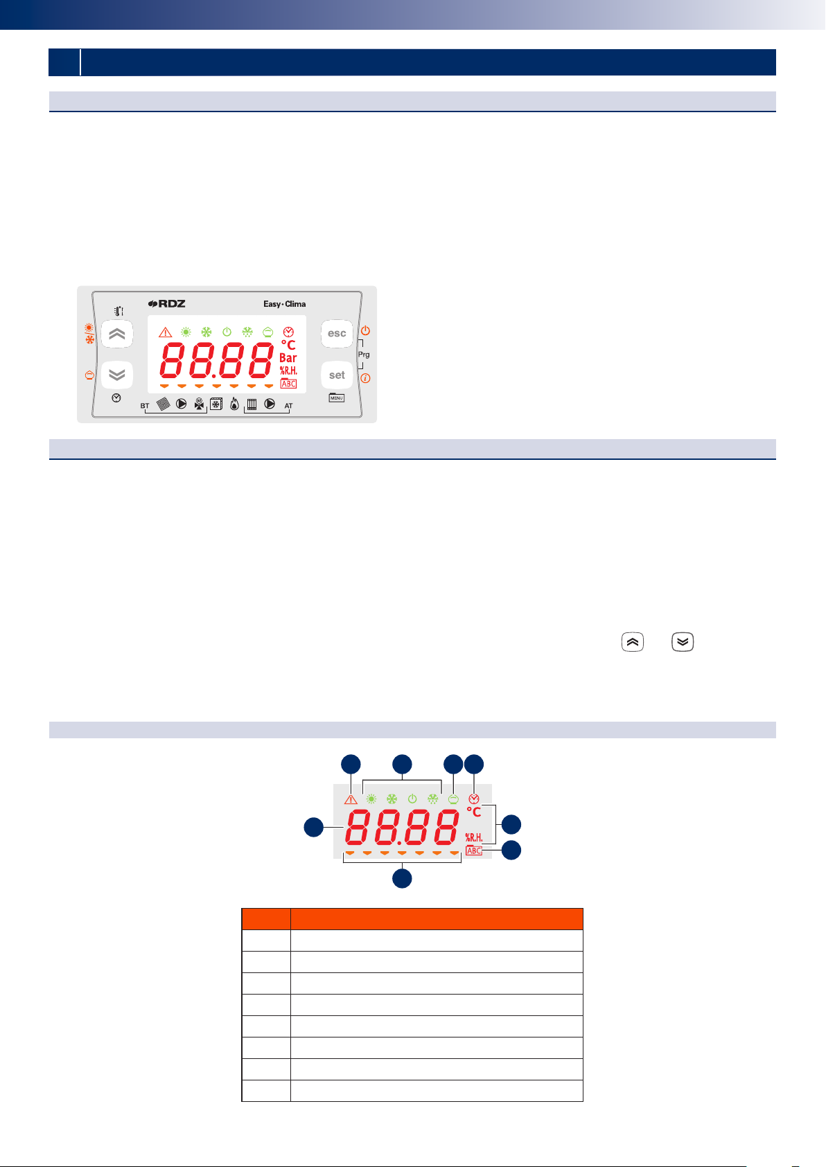
DISPLAY DESCRIPTION
The display is used to show the following information:
Main Display: value that can be set from parameter (as specied further on in this chapter).
Menu Navigation: the status folders, parameters, etc. can be accessed.
Within every folder, it is then possible to enter the sub-folders or parameters list
Alarms Display: the Alarm icon will switch on in the event of alarms.
When accessing the Alarms menu, see the corresponding Alarm Code displayed in alternating mode.
If there are several alarms simultaneously, the one with the lowest index will be displayed: using the and , keys it will be
possible to display the alarm codes present at the same time.
If the fundamental value is also in error mode, the Alarm icon will be displayed, along with the “Err” string or “Outr”.
DISPLAY KEY
Num Description
1Alarm icon
2Mode icon
3Economy icon
4Clock icon
5Unit of measurement of the value displayed
6Menu navigation icon
7Resources icon
8Values display
GENERAL DESCRIPTION
The “local” user interface of Easy Clima device consists in:
• Display showing temperature/pressure, time, menu/parameters labels and parameter values.
• Icons to display machine status, the unit of measurement of the value displayed and the state of the resources.
• Keys for menu navigation, to set parameters, to silence the alarms, to enter programming, and for the activation of the direct
functions.
The display of information and programming of the device via user interface are developed in menus with navigation using the
four keys as described in the relevant section.
7
1 3 42
5
6
8

6
Display icons table
Icon Description On with xed light On ashing
Cooling icon SUMMER = ON (Cool)
Heating icon WINTER = ON (Heat)
Stand-by icon STAND-BY = ON
Dehumidication icon DEHUMIDIFIER = ON
Economy icon ECONOMY MODE = ON
Alarm icon One or more alarms active
Time band operating icon Time band operating enabled
Display values values display
°C the value displayed is a temperature
value in °C
% R.H. the value displayed is % relative
humidity
Menu icon The menu is shown in the display
Low temperature system solenoid
valve icon
Low temperature system solenoid
valve = ON
POST-CIRCULATION in progress,
after the COOLING or HEATING
request has stopped
Low temperature system pump icon Low temperature system pump =
ON
POST-CIRCULATION in progress,
after the COOLING or HEATING
request has stopped
Modulating mixing valve
VMIX completely OPEN (Pos.=100%)
LED o = VMIX
completely CLOSED (Pos.=0% )
VMIX in OPENING or CLOSURE
mode, however in position dierent
to 100% or 0% and in movement.
3 point mixing valve
VMIX in OPENING mode (indicates
the opening “direction” of the
servomotor, NOT the duration of
the impulse towards the actuator)
VMIX in CLOSING mode (indicates
the closing “direction” of the
servomotor, NOT the duration of
the impulse towards the actuator)
Chiller icon CHILLER = ON
Boiler icon BOILER = ON
High temperature system solenoid
valve icon
High temperature system solenoid
valve = ON
POST-CIRCULATION in progress,
after the COOLING or HEATING
request has stopped
High temperature system pump High temperature system pump
= ON
POST-CIRCULATION in progress,
after the COOLING or HEATING
request has stopped
It is possible to decide which value to display in normal operating conditions (not in menu navigation mode, not in the event of
alarm signals) using the “SET/Info” key.

7
2SETTINGS
DESCRIPTION OF KEYS
Key Description
SET key
Short
press
• From the main display, access is given to the user set-point menu.
• From the operational parameters menu, the SET key allows you to:
- access to the menu sub-folders
- access to the value of any parameter of one of the menu sub-folders
- conrm the parameter and/or output value
Long press From the main display, access is given to the selection of the fundamental value to be displayed.
ESC key
Short
press
• With display o, the same is reactivated.
• Exit menus, list of parameters and parameter value (without saving the value) and go back to
the previous level
Long press From main display, the operating STATUS is changed from ON to STAND-BY and vice versa.
UP key
Short
press
• Scrolling the folders and parameters display upwards
• Parameter value increase
• From the main display, the room set adjustment is activated at the current time (heating or
cooling, comfort or economy) with ashing set value to be adjusted
Long press From main display, the operating condition is changed from heating to cooling and vice versa.
DOWN key
Short
press
• Scrolling the folders and parameters display downwards
• Parameter value decrease (if in parameter value modication mode)
• From the main display, the system date and time adjustment is activated.
Long press From the main display, if enabled, the operating MODE from ON-Comfort to ON-Economy and
vice versa.
+ access is given to the parameter and machine status menus folders.
DATE AND TIME
This chapter describes the screenshots that can be accessed by a short press of the key.
Screenshot Description
1
min
Minutes set
2
ora
Hour set
3
gior
Day set
4
mese
Month set
5
anno
Year set
N.B. in the event of a power cut lasting more than two days, the device loses the date and time setting. In this case, the values
must be reset.

8
00
••••
59
00
••••
23
01
••••
31
01
••••
12
00
••••
99
HOME
USER SETPOINT
This chapter describes the screenshots that can be accessed by a short press of the key.
set
appears on the DISPLAY. Use the and keys to scroll the items in the menu.
Use the key to conrm the selection and access the value of the item selected.
Use the and keys to adjust the value within the pre-dened elds.
Use the key to conrm the new value introduced.
Use the key, go back to the upper level until reaching the main display.
N.B. on the basis of the type of data, the temperature symbol or humidity symbol switches on, or no symbol
switches on (if it is a constant for example).
First level Second level Description of the third level screenshot
1
set
1
S_Hc
Comfort temperature set in winter mode
2
S_hr
Economy temperature set in winter mode
3
S_cc
Comfort temperature set in summer mode
4
S_cr
Economy temperature set in summer mode
5
S_um
Humidity set
2
cf
1
mode
Setting the ON or OFF operating mode to control the LT Area and the HT Area.
The VALUE eld means “ON” or “OFF”. If “OFF” is set, the main display will show “OFF”.
3
time
1
te00
Setting TIME BAND or NORMAL operation. The VALUE eld means “ON” or “OFF”.
If “ON” is set, the symbol switches on
4
hour
1
ore
Display of the operating hours of the LT Area Pump, the timer is shown on the DISPLAY
up to a maximum of 9999 hours.
2
rst
RESET procedure: “OFF” is shown, which can be switched to “ON” using the key.At this
point, pressing the key conrms the decision to reset the timer and then goes back
to “rst”.
5
all
Display of alarm codes in progress. See relevant paragraph.
ATTENTION:The set-point value will follow the trend of the room only in the presence of the Easy Clima Controller
installed. If this is not the case, the set-point set can aect the system ow temperature.
The humidity set-point will have no function if there is no humidity probe installed in the room.
DATETIME MODIFICATION PROCEDURE

9
MAIN VALUES SHOWN ON THE DISPLAY
In this chapter, select the data that will be displayed in the main screenshot and vary between the options described in the table
below.
Access the menu with a long press of the key, and then:
• by pressing the / keys, scroll the main values displayed
• by pressing the key, exit the menu
• by pressing the key, the value is transferred into the main screenshot and the menu is exited
First level Description
1
amb
The LT area room temperature value will start to ash after a few seconds.
If the room probe is congured but not connected or in short circuit conditions, ashing will be shown
Outr
on the DISPLAY.
If the room probe IS NOT congured, this screenshot will not be displayed
2
est
The external temperature value will start to ash after a few seconds.
If the external probe is congured but not connected or in short circuit conditions, ashing will be shown
Outr
on the DISPLAY.
If the external probe IS NOT congured, this screenshot will not be displayed.
3
umid
The LT area room humidity value will start to ash after a few seconds.
If the room probe is congured but not connected or in short circuit conditions, ashing will be shown
Outr
on the DISPLAY.
If the humidity sensor IS NOT congured, this screenshot will not be displayed
4
mand
The ow temperature value will start to ash after a few seconds.
If the ow probe is congured but not connected or in short circuit conditions, ashing will be shown
err
on the DISPLAY.
5
setm
After a few seconds the Set-Point calculated for the Area mixed system ow will start to ash.
6
pos
After a few seconds the current value of the position from 0% to 100% of the area 1 mixing valve starts
to ash.
7
ora
After a few seconds the time in progress is displayed in hours and minutes (e.g. 12:00) in a permanent way,
with the ashing.
8
Gior
After a few seconds the value of the day of the month in progress will be displayed (from 1 to 31)
9
mese
After a few seconds the value of the month in progress will be displayed.
10
anno
After a few seconds the value of the year in progress will be displayed.
The last two characters indicating the year are displayed (e.g. for 2011 will be displayed
11
).
.....
19.9 °C
20.0 °C
20.1 °C
.....
.....
16.9 °C
17.0 °C
17.1 °C
.....
.....
24.9 °C
25.0 °C
25.1 °C
.....
.....
27.9 °C
28.0 °C
28.1 °C
.....
.....
54.9 °C
55.0 °C
55.1 °C
.....
250
HOME
SETPOINT MODIFICATION PROCEDURE

10
For various reasons, mainly linked to the necessity to save energy, it is useful to be able to dierentiate device operation into
time bands.
The “time band” control is only relative to the LT Area system.
The device allows time band management, with the division of each day of the week into time periods (time bands) in which the
LT system controller can vary, on the basis of the program performed, from Comfort to Economy operating mode or in Stand-by.
EVENTS
The “event” concept is introduced to identify the various time bands.
For every event:
• The starting time (in hours and minutes)
• The operating mode that is activated (Comfort, Economy or Stand By
PROFILES
To distribute the various events per day of the week, the “prole” concept is introduced.
For every prole:
• The prole number (up to a maximum of 3 dierent proles can be dened)
• The distribution of the events within every prole, up to a maximum of 4 events for every prole
The prole to be associated can be specied for every day of the week. The default association will be “prole 1”.
Note: as the events available for every prole are HOWEVER 4, to disable an event (i.e. to reduce the number of time bands for
a specic prole), it will be sucient to give them the same start point and the same operating mode as the previous event.
PARAMETERS
To access the parameters modication described in the table below, follow the procedure given:
HOME
Mask Description U.M. Min Max Note Default
te00
Enabling of time band management Num On O O
WEEKLY
PROGRAMMING
te01
Prole selection, Monday Num 1 3
1 = Prole 1
2 = Prole 2
3 = Prole 3
1
te02
Prole selection, Tuesday Num 1 3 1
te03
Prole selection, Wednesday Num 1 3 1
te04
Prole selection, Thursday Num 1 3 1
te05
Prole selection, Friday Num 1 3 1
te06
Prole selection, Saturday Num 1 3 2
te07
Prole selection, Sunday Num 1 3 2
3TIME BAND MANAGEMENT
N.B. On Easy Clima Controller display TE01, TE02, ... TE07 screenshots are called MON, TUE, WED, THU, FRI, SAT, SUN
Table des matières
Autres manuels RDZ Contrôleurs


