RDS P332 Manuel utilisateur

P
PP
P3
33
332 RDS Encoder
32 RDS Encoder32 RDS Encoder
32 RDS Encoder
Quick Installation Guide
Web: http://www.pira.cz/rds/ E-mail: [email protected]z

2
Table of Contents
1
Using This Guide ............................................................................................................................................................................................... 3
1.1
Purpose.......................................................................................................................................................................................................... 3
1.2
Additional ocumentation .............................................................................................................................................................................. 3
1.3
isclaimer....................................................................................................................................................................................................... 3
2
Physical Description ......................................................................................................................................................................................... 4
2.1
Front Panel..................................................................................................................................................................................................... 4
2.1.1
Status LC ............................................................................................................................................................................................... 4
2.1.2
LE indicators.......................................................................................................................................................................................... 5
2.2
Rear Panel ..................................................................................................................................................................................................... 5
3
Hardware Installation ........................................................................................................................................................................................ 6
3.1
Connecting the R S Encoder........................................................................................................................................................................ 6
3.2
Hardware Settings.......................................................................................................................................................................................... 7
3.2.1
On-board adjustable elements................................................................................................................................................................. 7
3.2.2
Loop/Side switch...................................................................................................................................................................................... 7
3.3
Power Supply ................................................................................................................................................................................................. 8
3.4
Connecting the R S Encoder to a Local PC or a CE evice ..................................................................................................................... 8
3.4.1
Connection to a serial port of the PC....................................................................................................................................................... 8
3.4.2
Connection to a CE device.................................................................................................................................................................... 8
3.4.3
Connection to a USB port of the PC ........................................................................................................................................................ 8
3.5
R S Level Adjustment................................................................................................................................................................................... 9
4
oftware Installation........................................................................................................................................................................................ 10
4.1
Establishing a First Communication with the R S Encoder ........................................................................................................................ 10
4.2
Remote Configuration of the R S Encoder................................................................................................................................................. 11
4.2.1
Finding out actual R S encoder’s IP address....................................................................................................................................... 11
4.2.2
Remote configuration of the R S encoder using internal website ........................................................................................................ 11
4.2.3
Remote configuration of the R S encoder using the Windows control software .................................................................................. 11
4.3
evice Setup................................................................................................................................................................................................ 12
4.3.1
evice Setup from the Magic R S ........................................................................................................................................................ 12
4.4
Setting Basic R S ata ............................................................................................................................................................................... 14
4.4.1
PI (Program Identification) ..................................................................................................................................................................... 14
4.4.2
PS (Program Service name).................................................................................................................................................................. 14
4.4.3
PTY (Program Type).............................................................................................................................................................................. 14
4.4.4
TP (Traffic Program) .............................................................................................................................................................................. 15
4.4.5
MS (Music/Speech)................................................................................................................................................................................ 15
4.4.6
AF (Alternative Frequencies) ................................................................................................................................................................. 15
5
Broadcast Automation ystem Link-up ........................................................................................................................................................ 16
5.1
Indirect Link.................................................................................................................................................................................................. 16
5.2
irect Link .................................................................................................................................................................................................... 16
5.2.1
Recommended procedure step-by-step................................................................................................................................................. 16
5.2.2
Compatibility commands and UECP...................................................................................................................................................... 16

3
1 Using This Guide
1.1 Purpose
This guide covers P332-based R S encoders (both module and boxed versions). It provides the information needed to install the equipment
and set basic R S services in order to get your station R S enabled quickly in a few steps.
Please read this entire guide and familiarize yourself with the controls before attempting to use this equipment.
Where not otherwise indicated, any information mentioned in relation to the RD (Radio ata System) applies in full also to the RBD (Radio
Broadcast ata System).
If you have any questions or comments regarding this document, please contact us via email.
We welcome your feedback.
1.2 Additional Documentation
Browse the installation C or visit the Website for the latest documentation version and the following additional documentation:
• P132 Communication Ports and Internet Functions
• P332 R S Encoder Technical Manual (includes troubleshooting on the last page)
• Magic R S Help
• Magic R S Guide – How to... (http://pira.cz/rds/show.asp?art=magic_rds_how_to)
• Support section (http://pira.cz/rds/show.asp?art=rds_encoder_support)
1.3 Disclaimer
The equipment has been thoroughly tested and found to be in proper operating condition when shipped. The manufacturer is not liable for any
damages, including but not limited to, lost profits, lost savings, or other incidental or consequential damages arising out of the use of this product.
No part of this manual may be reproduced or transmitted in any form or by any means, electronic or mechanical, including photocopying, recording
or information storage and retrieval systems, for any purpose other than the purchaser's personal use.
Information in this document is subject to change without notice.
Revision 2015-09-19
Copyright © 1999-2015 PlRA igitaI s.r.o.

4
2 Physical Description
2.1 Front Panel
2.1.1 Status LCD
The LC area is divided into two lines.
The first line shows key R S services which require quick access. These services are PS (incl. dynamic), PI, TP and TA.
The second line shows the most important status values and R S services in a loop. epending on the configuration, some values may be
omitted. For example if the internal clock source is set for the R S subcarrier, the PILOT value is not showed. Some events may affect the
order. For example if Radiotext changes, it's showed in the next cycle regardless of previous order.
Order tatus value or
RD service Meaning Default value
1 R SGEN ON = R S generator enabled (1), OFF = no R S output (0). ON
2 LEVEL Output R S signal level (0 = min., 255 = max.). 255
3 PROGRAM Actual program set selected. 1
4 PTY, MS, I Program Type code; Music/Speech; ecoder Identification code.
5 A R The UECP address list. 0,0
6 SITE The UECP site list. 0,0
7 UECP ON = The R S encoder accepts both ASCII and UECP commands,
OFF = the R S encoder accepts ASCII commands only. OFF
8 IPA Shows actual IP address of the encoder, assigned either manually or by the
HCP function.
9 SPEE Actual RS-232 port speed on which the control commands are expected.
10 PILOT ON = pilot tone present, OFF = no pilot tone.
11 CT ON = CT enabled, OFF = CT disabled; R S encoder’s local time.
12 GRPSEQ First 16 items of R S group sequence. 022E1022EA022XYR
13 RT Actual Radiotext (sequence of 4 x 16 characters).
TP
PS
PI
TA

5
2.1.2 LED indicators
Two LE diodes are used to indicate operating status of the R S encoder:
Pilot LED Operation LED tatus
on off Initialization
Start-up off on Firmware update in progress
· · · · · Normal operation
- - - - -
An error occurred (encoder’s hw failure)
on Receiving data on some port
on External pilot synchronization is active
off Internal clock source is selected
Operation
- - - - -
Stereo encoder error - pilot tone present but does not meet
the specification required.
Solution: Switch the R S encoder to internal clock source.
2.2 Rear Panel
ETHERNET RS-232 OUTPUT INPUT GPIO12V DC
LOOP SIDE
Connector or element Desctiption
12V C Power Supply Power supply connector. See section 3.3 for details.
Ethernet Ethernet RJ-45 connector.
Use a standard (direct) cat 5 Ethernet cable for connection to the Ethernet switch, router or wall-socket.
The Ethernet control includes internal website (referenced as “Port 2”) and two independent user
configurable general purpose ports (referenced as “Port 3” and “Port 4”) designated for remote control via
TCP or U P protocol.
The encoder operates also with no cable connected.
RS-232 RS-232 standard male type connector. This port is referenced as “Port 1”.
If you cannot reach the R S encoder over the LAN, use the RS-232 for initial setup of the encoder or for its
local control. For wiring, see the section 3.4.
The port is internally optically isolated from the rest of the encoder’s circuitry to prevent ground
loops and to keep high E D immunity and EMC.
The encoder operates also with no cable connected.
Output BNC R S signal output, modulated at 57 kHz subcarrier.
If the Loop/Side switch is set to the LOOP position, the Output is a sum of the R S signal and the signal fed
to the Input BNC connector.
Input BNC Optional input for synchronization to the pilot tone or for mixing the R S signal with existing modulation
signal.
Loop/Side switch Allows the input signal to be added to the output signal. See sections 3.1 and 3.2 for details.
GPIO Optional logical inputs for direct control of some R S services (TA, PROGRAM).
See the Technical manual for details. The connector is a standard 6-pin PS/2 type.

6
Hardware Installation
3.1 Connecting the RDS Encoder
Basic rules applying for any R S encoder’s connection:
The R S signal must be fed into modulation input (added to MPX signal if stereo encoder is used).
If stereo encoder is used, one of its outputs (MPX or pilot tone) must be fed into the R S encoder input to meet the synchronization
requirement.
Following figures show various situations and corresponding methods of connection. Use shielded cables (e.g. RG58) terminated by BNC male
connectors. The cables should be kept short in length. Where necessary, use a BNC ‘T-piece’ for splitting the signal.
Stereo encoder
FM Trans itter
RDS Encoder
MPX inputRDS/SCA/MPX input
Pilot/MPX outputMPX output
Separate stereo encoder - default connection.
Stereo encoder
FM Trans itter
RDS Encoder
MPX input
MPX output
RDS/SCA/MPX input
Stereo encoder with only one MPX output provided.
Stereo encoder
FM Trans itter
RDS Encoder
MPX output
MPX input
RDS/SCA input
FM transmitter with only one MPX input provided.

7
Stereo encoder
FM Trans itter
RDS Encoder
MPX input
MPX output
Both stereo encoder and FM transmitter with only one MPX connector provided - loopthrough mode.
Use this mode only if no of the previous connections is possible.
FM Trans itter with
integrated stereo encoder
RDS Encoder
Pilot/MPX outputRDS/SCA/MPX input
FM transmitter with integrated stereo encoder.
In case of mono transmission (no stereo encoder used) the R S encoder input may be left unconnected (since there is no need of external
synchronization) or it may be used for the audio signal injection in the case that the FM transmitter has only one input connector.
3.2 Hardware Settings
.2.1 On-board adjustable elements
ue to completely SP-based solution there’s no adjustable element on the board affecting the R S or MPX signal.
User is not allowed to open the encoder’s case.
.2.2 Loop/Side switch
Select the LOOP position only if it’s necessary to pass the input signal to the output of the R S encoder (loopthrough mode).
In all other cases the switch must be fixed in the IDE position!
Always make sure that the switch is securely fixed in the position desired and eliminate possibility of unwanted change of its state!
8
3.3 Power Suppl
The R S encoder can be supplied from any power supply, which delivers a stabilized 12 V voltage and a current of at least 500 mA.
Commonly available switching wall adapters are usually suitable for that purpose. The R S encoder includes polarity and short-circuit
protection. The central conductor of the power supply connector is positive (+).
Note: After first power-up, there is no need to configure anything to turn on the RDS subcarrier. The RDS encoder will i ediately start to
generate the RDS signal with factory default values (PS: * RDS *, PI: FFFF, RDS level: set to axi u 4000 V p-p).
3.4 Connecting the RDS Encoder to a Local PC or a DCE Device
For the purpose of initial configuration and local or special control requirements the R S encoder is equipped with standard RS-232 interface
provided on -SUB9 male connector on the rear panel of the R S encoder. This connector allows direct connection to a PC using a standard
serial laplink cable (null-modem, crossed) or USB cable with built-in RS-232 converter.
.4.1 Connection to a serial port of the PC
On the PC side locate an unused COM port. If the free port exists in the form of a 25-pin connector, use a standard -SUB9 (male) to -
SUB25 (female) adapter. Make sure the COM port is enabled in the PC’s BIOS Setup.
RD Encoder PC
2 (RxD) 3 (TxD)
3 (TxD) 2 (RxD)
4 ( TR) 6 ( SR)
5 (GND) 5 (GND)
6 ( SR) 4 ( TR)
7 (RTS) 8 (CTS)
8 (CTS) 7 (RTS)
It’s preferable to use standard serial laplink cable terminated with 9-pin female connector on the PC side and 9-pin female connector on the
R S encoder side. The table above represents the full connection diagram. In most cases (no flow control) the three highlighted wires are
enough for the connection.
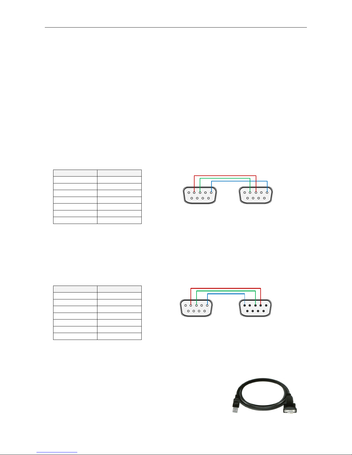
.4.2 Connection to a DCE device
This kind of connection applies to most data sources equipped with -SUB9 female connector.
RD Encoder DCE
2 (RxD) 2 (TxD)
3 (TxD) 3 (RxD)
4 ( TR) 6 ( SR)
5 (GND) 5 (GND)
6 ( SR) 4 ( TR)
7 (RTS) 8 (CTS)
8 (CTS) 7 (RTS)
It’s preferable to use standard direct RS-232 cable terminated with 9-pin female connector on the CE side and 9-pin male connector on the
R S encoder side. The table above represents the full connection diagram. In most cases (no flow control) the three highlighted wires are
enough for the connection.
.4. Connection to a USB port of the PC
Connection to USB port of your PC is possible via standard USB to RS-232 cable. It is also known
as USB to RS-232 adapter. A serial laplink cable is also required to be present in the chain.
USB driver must be installed prior to start communicating. Virtual COM port feature provides
seamless compatibility with broadcast automation software.
1 2 3 4 5
6 7 8 9
DB9 male
5 4 3 2 1
9 8 7 6
DB9 female
1 2 3 4 5
6 7 8 9
1 2 3 4 5
6 7 8 9
DB9 male DB9 male

9
3.5 RDS Level Adjustment
Important note: There is no universal setting for the RDS level. Due to different input sensitivity of different FM broadcast equip ent it's
necessary to check and adjust the RDS level!
The correct level should be between 2 and 11 % of the audio multiplex signal, measured by oscilloscope in peak-to-peak values on the
modulator input. Recommended value is such that results in 3.4 kHz deviation of the FM carrier. on’t forget that the maximum total FM carrier
deviation with R S and MPX signal is 75 kHz. It is much easier to use an FM broadcast analyzer for setting the R S level precisely.
The R S level can be adjusted after establishing a connection to the encoder, using one of these two methods:
In the Windows software
Go to Options – Preferences – Control and check the item ‘Enable R S level control’. Now the control is available on the System sheet in the
main window.
The software allows adjusting the R S level in range 0.4 to 100 %. In the P332 R S encoder, that range is proportional to the output level
range of 15.6 to 4000 mV p-p. Confirm the setting by Store button.
In the embedded website
Click on menu item Setup – Signal Control and enter the R S level directly in mV p-p unit.
In terminal, using A CII command LEVEL=
The P332 R S encoder allows direct adjusting of the R S level in 256 steps, in range 0 to 255, by assigning a corresponding value to the
LEVEL parameter. Each step represents approx. 15.6 mV increase.
esired step count can be calculated as
1
4000
256 −
×= levelRDSOutput
LEVEL
Actual output R S level (in mV p-p) can be calculated as
4000
256
1×
+
=LEVEL
levelRDSOutput
The deviation range of the FM carrier caused
by R S/RB S
is
1.0
to
7.5
kHz
.
The deviation range of the FM carrier caused by stereo pilot tone is 6.0 to 7.5 kHz.
The overall peak frequency deviation shall not exceed 75 kHz.

10
4 Software Installation
4.1 Establishing a First Communication with the RDS Encoder
The R S encoder should be configured via local port (port 1) before first use. Alternatively, the configuration can be made using the embedded
website.
The encoder comes initialized from the factory. The Ethernet is pre-configured in order to obtain IP address from HCP. Thus, in the HCP
enabled environment, the first connection with the encoder can be established using a web-browser and typing the assigned IP address into
the address field. See more details in section 3.1 of the document ‘P132 R S Encoder – Communication Ports and Internet Functions’.
For local configuration via port 1, please follow these steps:
1. Install the Windows control software called ‘Magic R S’, run the setup exe file and go through the simple installation wizard.
2. In the case of using USB adapter, install the USB driver now.
3. Make sure the R S encoder is connected and powered, and all connectors are seated completely.
4. Run the Magic R S software using Windows Start button.
5. Open the Preferences (Options - Preferences) and set up the connection parameters. Choose the Serial RS232/USB connection type
and select the COM port the R S encoder is connected to. If the R S encoder is connected via USB and was recognized correctly in
Windows, you may find/change the COM port number in Windows Control Panels - System - Hardware - evice Manager or simply click
on the List button.
6. Close the Preferences. You should see "Connected" or "Opened" in the status bar. Now you are ready. The settings are saved
automatically.
7. The status bar at the bottom of the window shows whether the data was sent successfully. If Communication Error! is shown, check the
connection to the R S encoder, its power supply and that the correct COM port is selected in the Preferences dialogue box.
8. Follow the instructions from the application Help.
Note: The RDS encoder contains two types of e ory. These are arked as RAM and EEPROM. Like any other co puting syste the RAM
holds all operational data which are also used for trans ission whilst the EEPROM is used for the data storage during power-off. By default the
button Send will fill the RAM only. The button Store will fill the RAM and also stores the data into EEPROM. The Store button behavior can be
changed in Options - Preferences - Controls.
If the user forgets to store the data into EEPROM, the settings will be lost when the power is disconnected.
Autres manuels pour P332
1
Table des matières
Autres manuels RDS Convertisseur de média


