RDS Technology Artemis 100 Manuel utilisateur

1
Artemis 100
Variable Rate Drill Controller
Calibration and Operation
Software
Reference A500.000 rev. 7
Electro-Magnetic Compatibility (EMC)
This product complies with Council Directive
89/336/EEC when installed and used in accordance
with the relevant instructions.
Service and Technical Support
PLEASE CONTACT YOUR NEAREST DISTRIBUTOR
If unknown then fax: 44 (0) 1453 733322
© Copyright RDS Technology Ltd 2001
Document number
S/DC/500-10-310 : Issue 1 : 4/7/01
\UK310-1.DOC
User Guide

ARTEMIS 100 – VARIABLE RATE DRILL CONTROLLER
2
Contents
Overview_______________________________________________4
Operating Summary ____________________________________5
Power On/Off................................................................................................................. 5
Switch Functions........................................................................................................... 5
Normal Display Mode ___________________________________6
Programming Modes.................................................................................................... 6
Work Status Indicator ................................................................................................... 6
AForward Speed Display____________________________7
A.1 View Forward Speed ......................................................................................... 7
A.2 Speed Alarms ......................................................................................................... 7
A.3 Speed Sensor Calibration...................................................................................... 7
Manual Calibration........................................................................................................ 8
Auto Calibration ............................................................................................................ 9
BArea Display ____________________________________10
B.1 View Area Totals ..............................................................................................10
B.2 Zero Area Total................................................................................................. 10
B.3 Set Implement Width .......................................................................................11
C. Drilling Rate Functions___________________________12
C.1 View Drilling Rate ............................................................................................. 12
C.2 Adjusting the Drilling Rate............................................................................... 12
C.3 Drilling Rate Indicator ......................................................................................12
C.4 Changing the Target Rate ...............................................................................13
C.5 Set Current Rate to become new Target Rate ..............................................13
C.6 Product Calibration.......................................................................................... 14
C.7 Set "Thousand Grain Weight".......................................................................... 15
C.8 Select Unit ........................................................................................................16
C.9 Set % Step for Rate Offset...............................................................................16
C.10 Frequently asked Questions ...........................................................................17

ARTEMIS 100 – VARIABLE RATE DRILL CONTROLLER
3
D. Fan Speed Display ______________________________ 18
D.1 View Fan Speed............................................................................................... 18
D.2 Fan Under-Speed Alarm ................................................................................. 18
D.3 Fan Over-speed Alarm .................................................................................... 18
D.4 Set Low Fan Speed Alarm.................................................................................. 19
E. Tramlining______________________________________ 20
E.1 Manually advance bout number..................................................................... 20
E.2 Hold Bout number........................................................................................... 20
E.3 Symmetrical Tramlining .................................................................................. 21
E 4.1 Asymmetrical Left Tramlining........................................................................... 22
E 4.2 Asymmetrical Right Tramlining....................................................................... 23
E 4.3 10-bout Tramlining............................................................................................ 24
E 4.4 18-bout Tramlining........................................................................................... 25
E.5 Programme Tramline Bout .................................................................................. 26
F. Hopper level Alarm _____________________________ 28
G. Programme Functions and Fault Diagnosis _______ 29
G.1 Programme Modes 1 –4.................................................................................. 29
G.2 Error Codes...................................................................................................... 30
G2.1 Alarms irrespective of "Work" Status ................................................ 30
G.2.2 Alarms when the drill is in work........................................................ 31

ARTEMIS 100 – VARIABLE RATE DRILL CONTROLLER
4
Overview
The Artemis 100 Drill Control is a CAN Bus control system suited for both
conventional and pneumatic drills. The system has two CAN Modules - one
for controlling the electric motor driving the metering unit, and another
controlling the various sensor inputs and tramlining outputs. All the
components are connected via a custom wiring loom. The cab instrument
has a 6-way Amphenol sealed connector allowing it to be easily
disconnected and transferred to another drill as required. A separate heavy
duty power cable powers the CAN Modules and motor. An in-line heavy duty,
quick-release connector simplifies mounting and dismounting the drill.
The metering unit is controlled via an electric motor, allowing the drilling rate
to be varied at the touch of a button. The drilling rate can be varied in 5% or
greater steps from the pre-programmed target rate.
The instrument measures and indicates;
•Forward Speed
•Part Area and Total Area worked
•Tramline bouts
•Seed Application Rate (kg/ha or Seed/m2)
•Fan Speed
•Low Hopper Level
The instrument has a number of alarm functions for fan over-speed, forward
over-speed and under-speed, and hopper level. In addition, a number of
extra alarms are displayed as fault codes.
The instrument must be initially calibrated to suit the implement being
controlled. Seed calibration is very simple to undertake via a priming switch
provided on the drill. Other default settings are also programmable in the
calibration mode.
Area totals and all calibration data are automatically stored in memory when
the instrument is powered off.

ARTEMIS 100 – VARIABLE RATE DRILL CONTROLLER
5
Operating Summary
Power On/Off
Switch the system on/off via the toggle switch on the rear of the head unit.
Switch Functions
Current Bout
Press to select
the Display
Function
Decrease
Rate
Channel
Indicator
At Target rate
Indicator
Increase
Rate
Preset Tramlining
bout Indicator
EITHER:
1. View Area Total
Select the channel then
press to switch
between Area Total 1 and
Area Total
2. Advance Bout Number
Select the channel then
press to manually
advance the Bout Number.
3. Set Target Rate
Select the channel then
press and hold to
display rate. Use +RATE and
-RATE to adjust.
4. HOLD continuously to
enter Programme mode 1 /
Programme Mode 2
(Normal Mode is resumed
when the button is released).
CH Function Units
1Forward Speed km/h
2Area Total 1 or 2 ha
3Tramline/Current bout -
4Seed Rate kg/ha or seeds/m2
5Fan Speed rpm
6Hopper level alarm 'lo.1, lo.2'
These channels perform different functions
when the instrument is set in to Programme
Modes 1, 2, 3, or 4
Increase Rate
Or,
HOLD whilst
powering on to
enter CAL Mode 2
(for automatic
product
calibration)

ARTEMIS 100 – VARIABLE RATE DRILL CONTROLLER
6
Normal Display Mode
The instrument has a normal display mode displaying six work functions
Select a channel by pressing the button once or more.
When the drill is in work, the selected channel is displayed for 10
seconds before defaulting back to the tramline bout display
( channel).
When the drill is out of work, the instrument will continue to display the
selected channel.
Programming Modes
There are 4 programming modes with various calibration factors and default
settings.
Access to the programming modes is required for some settings which are
changed as part of the normal operating procedure (such as product
calibration). Changing these settings is described within the normal operating
instructions (sections A, B, C, C, D, E and F).
Other settings are made on installation and do not normally need to be
changed unless the instrument is switched onto a different drill. These settings
are appended to in the back of this manual (section G). The operator does not
normally need to refer to them.
Work Status Indicator
The indicator is used to indicate the channel to which the information on
the display relates.
It also shows the working status of the drill. If the cursor is flashing then the
drill is out of work, if the cursor is solid then the drill is in work.
ARTEMIS 100 – VARIABLE RATE DRILL CONTROLLER
7
AForward Speed Display
A.1 View Forward Speed
The forward speed is derived either from an
encoder on the landwheel, or from a radar
sensor
depending on your particular installation.
The speed is displayed in km/hr only.
A.2 Speed Alarms
(i) If you stop with the drill still in work, the
instrument will beep twice, and the display
alternates between the selected channel and
the forward speed channel, until you start
moving again.
(ii) If you drive too fast, the motor control will be
unable to maintain the required seed rate.
Again, the instrument will default to the
speed channel, the display will flash "HIGH"
and the instrument will beep until you slow
down. The maximum forward speed is
calculated by the software for the seed rate
being achieved.
A.3 Speed Sensor Calibration
The forward speed is derived from the
distance travelled in millimetres for each
pulse received from the speed sensor. The
speed sensor is either a rotary encoder on
the landwheel, or a radar sensor.
You can either calculate and manually enter
the Speed Sensor Factor (S.S.F.) or do an
"Autocal".
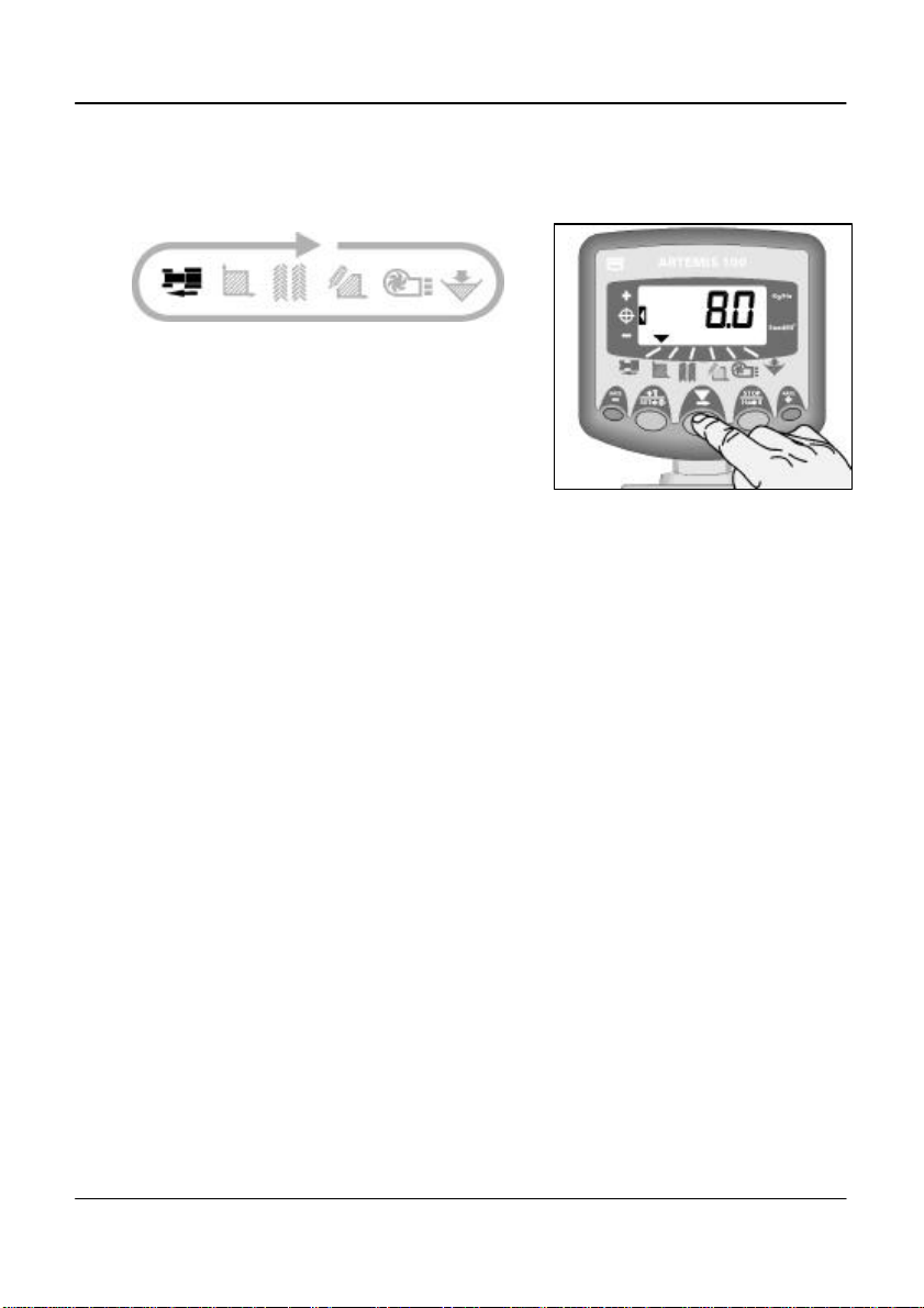
Figure 1 : Select Fwd. Speed

ARTEMIS 100 – VARIABLE RATE DRILL CONTROLLER
8
Manual Calibration
If a rotary encoder is fitted, the theoretical
calibration figure equals the rolling
circumference of the land wheel in
millimetres divided by the pulses per rev. of
the encoder,
e.g. diameter (mm) x 3.142
360
The cal factor should normally be a figure
around 10 (mm/pulse).
If a radar sensor is fitted, then accept the
default factor of 7.78 mm/pulse for the RDS
radar sensor.
To manually enter the calibration factor:
1. Select the forward speed channel (fig. 2).
2. Press and hold the button until the cal
factor appears on the display (fig 2).
3. Continue holding the button and
PRESS to select the digit/decimal point
to change (fig. 3).
4. HOLD to change the digit (or move the
decimal point). Releasing the button selects
the next digit.
5. Release the button to return to the
normal display mode.
Failure to correctly programme the speed
sensor factor will result in the drilling rate
being displayed incorrectly. Auto calibration
is likely to be more accurate than manual
calibration.
Figure 2 : Enter CAL Mode 1 (S.S.F.)
Figure 3 : Change S.S.F.
2 1
2 43

ARTEMIS 100 – VARIABLE RATE DRILL CONTROLLER
9
Auto Calibration
Auto-calibrate in field conditions for
maximum accuracy.
1. Place two markers 100 metres apart and
position some reference point on the tractor
(e.g. the cab step), opposite the first
marker.
2. Select the forward speed channel.
3. Press and hold the button until the cal
factor appears on the display.
4. Continue holding the button and press
the button. The display will show "AUto"
ready to start the test run (fig. 4).
5.Drive up to the second marker and stop
exactly opposite the marker. The instrument
counts and displays the pulses received
from the speed sensor over the measured
distance.
NOTE: The instrument only displays up to 9999
pulses then cycles back to 0000, however
the pulses are still being counted internally.
6. Press the button (fig. 5). The calibration
factor is automatically calculated and stored
in memory. The instrument then returns to
the normal display mode.
Figure 5 : Stop Autocal
Figure 4 : Start AutoCal
100 metres
6
5
3 4

ARTEMIS 100 – VARIABLE RATE DRILL CONTROLLER
10
BArea Display
B.1 View Area Totals
The area display is derived from the forward
speed sensor and the programmed
implement width.
There are two area registers. Each can be
independently reset to zero.
Press to cycle between the two area
registers 'tot.1' and 'tot.2'.
The display then shows the area
accumulated since that total was last reset.
B.2 Zero Area Total
1. Select the total 1 or total 2 and release.
2. HOLD for 5 seconds.
The instrument gives 10 beeps, then the total
resets to zero.
Figure 8 : Zero Area Total
Figure 7 : Select Area Register 1 / 2
Figure 6 : Select Area Channel
1 2
Table des matières
Autres manuels RDS Technology Contrôleurs


