Raymarine SeaTalk Joystick Manuel technique

1
Document Number 81227-2
June 2005
Raymarine SeaTalk Joystick
Introduction
Thank you for choosing Raymarine.This booklet contains installation, calibration
and operation instructions for your Joystick. To get the best from your product,
please take time to read these before use.
Autopilot Compatibility
The SeaTalk Joystick is compatible with Raymarine SmartPilots and Course
Computers with software version 3 or later. Use the procedures in the
maintenance chapter of the Autopilot Operating Guide to find out the software
version on your system. If you have pre-version 3 software, contact your local
Raymarine dealer for assistance.
Warranty
To register your new Raymarine product, please take a few minutes to fill out the
warranty card. It is important that you complete the owner information and
return the card to us to receive full warranty benefits.
83 mm (3.27 in)
88 mm (3.5 in)
110 mm (4.33 in) 110 mm (4.33 in)
D6413-1
51 mm (2 in)
219 mm (8.6 in)
152 mm (6 in)
81227_2.book Page 1 Wednesday, November 2, 2005 10:51 AM

2
EMC Conformance
All Raymarine equipment and accessories are designed to the best industry
standards for use in the recreational marine environment. Their design and
manufacture conforms to the appropriate Electromagnetic Compatibility (EMC)
standards, but correct installation is required to ensure that performance is not
compromised.
Parts supplied and tools required
Parts supplied
Tools required
Power Drill
SeaTalk
Joystick Gasket
Joystick pod
Thumb nut
(4 off)
Stud
(4 off)
2m SeaTalk cable1m Joystick cable
No.6 x 3/4 in pan-head
self-tapping screw (3 off)
Jigsaw
5mm (3/16 in) Drill
D6415-1
Pozi-drive
screwdriver
81227_2.book Page 2 Wednesday, November 2, 2005 10:51 AM

Raymarine SeaTalk Joystick 3
WARNING: Product installation
This equipment must be installed and operated in accordance
with the instructions contained in this handbook. Failure to do so
could result in poor product performance, personal injury and/or
damage to your boat.
As correct performance of the boat’s steering is critical for safety, we STRONGLY
RECOMMEND that an Authorized Raymarine Service Representative fits this
product. You will only receive full warranty benefits if you can show that an
Authorized Raymarine Service Representative has installed or commissioned this
product.
WARNING: Electrical safety
Make sure the power supply is switched off before you make any
electrical connections.
Product disposal
Waste Electrical and Electronic (WEEE) Directive
The WEEE Directive requires the recycling of waste electrical and
electronic equipment.
Whilst the WEEE Directive does not apply to some of Raymarine's products, we
support its policy and ask you to be aware of how to dispose of this product.
The crossed out wheelie bin symbol, illustrated above, and found on our products
signifies that this product should not be disposed of in general waste or landfill.
Please contact your local dealer, national distributor or Raymarine Technical
Services for information on product disposal.
81227_2.book Page 3 Wednesday, November 2, 2005 10:51 AM
4
1.1 Joystick operation
CAUTION:
Before use, familiarize yourself with joystick operation. On power
boats, always gain experience at low speeds before using the
joystick at higher speeds.
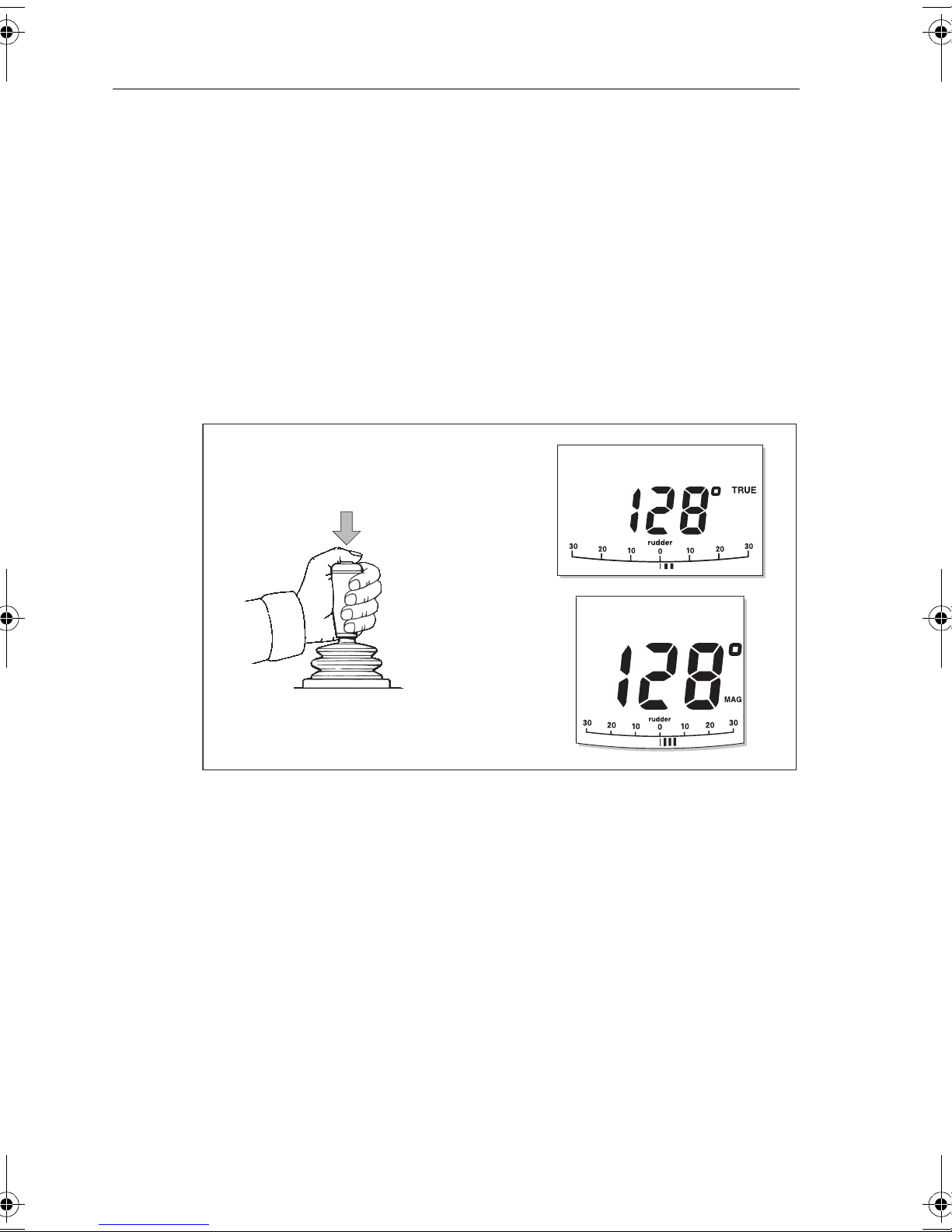
Basic operation
To engage joystick control, press the control button (located on top of the lever)
once. The autopilot will then display MANUAL (ST6001 controllers) or PWR STEER
(ST7001 & 8001 controllers) along with the current heading.
The joystick operates in two modes, Normal proportional mode which is the
default and “bang-bang” mode. Both modes are described below. You can select
which mode will be used in
Setting up your Joystick
on
page 11
.
Normal Proportional mode (default)
Proportional mode applies rudder in proportion to joystick movement. The further
the joystick is held over the greater the applied rudder (see illustrations on next
page).
D6423-1
PWR STEER
MANUAL
MANUAL
ST6001
ST7001
ST8001
81227_2.book Page 4 Wednesday, November 2, 2005 10:51 AM

Raymarine SeaTalk Joystick 5
Large Helm Angle
Small Helm Angle
D6424-1
Proportional mode - applying port rudder
PWR STEER
PWR STEER
D6425-1
Large Helm Angle
Small Helm Angle
Proportional mode - applying starboard rudder
PWR STEER
PWR STEER
81227_2.book Page 5 Wednesday, November 2, 2005 10:51 AM

6
Bang-Bang mode
Bang-Bang (drive left – drive right) mode applies continuous rudder drive in the
direction of joystick movement. To improve control, the speed of rudder
movement changes with the angle of the lever: for maximum speed push the
lever hardover. If the lever isreturned to the center position the rudder will remain
in its current position.
D6426-1
Bang-Bang mode - applying port rudder
PWR STEER
D6427-1
Bang-Bang mode - applying starboard rudder
PWR STEER
81227_2.book Page 6 Wednesday, November 2, 2005 10:51 AM

Raymarine SeaTalk Joystick 7
1.2 Installation
Overview
The diagram below gives an overview of how the joystick can be connected to
your SeaTalk system.
Follow the procedures on the following pages to install and set-up your SeaTalk
joystick.
Joystick Pod
RedYellowScreen RedYellowScreen
SeaTalkSeaTalk
or
SmartPilot Computer
To SeaTalk
compatible device
D6420-1
1m Joystick
interface cable
81227_2.book Page 7 Wednesday, November 2, 2005 10:51 AM

8
Step 1 - Mounting the Joystick
The mounting surface must be smooth and flat to ensure that there is adequate
waterproofing.
1. Use the template provided at the rear of this booklet to mark the centers for
the fixing holes and outline of the body aperture.
2. Drill the fixing holes and cut-out the aperture for the body.
3. Peel off the protective paper from the rear of the weather gasket and fix to the
joystick.
4. Secure the joystick with the thumb nuts provided.
5. Plug in the interface cable to the base of the joystick
D6414-1
Forward
81227_2.book Page 8 Wednesday, November 2, 2005 10:51 AM

Raymarine SeaTalk Joystick 9
Step 2 - Mounting the joystick pod
CAUTION:
The Joystick pod is not waterproof and so must be installed in a
dry location.
The Joystick pod must be positioned in a dry location where:
• It is protected against physical damage.
• Is within reach of the joystick interface cable (less than 0.9m from joystick)
• It is at least 9 in (230 mm) from a compass.
• It is at least 20 in (500 mm) from radio receiving equipment.
• There is reasonable access for installation and servicing.
To mount the Pod:
1. Remove the Pod cover.
2. Place the Pod, with the single connector area uppermost on themounting sur-
face and mark the centres of the fixing holes.
3. Drill three pilot holes for the Pod mounting screws, then secure the Pod to the
mounting surface with the screws provided.
D5543-1
81227_2.book Page 9 Wednesday, November 2, 2005 10:51 AM

10
Step 3 - Wiring the Joystick pod
The Pod connectors are color-coded, so ensure that each wire is connected to the
correspondingly-colored connector. Make the connections as shown below. Once
complete, replace the Pod cover.
1 Fit SeaTalk cable 2 Press Joystick interface cable into
cable channel
3 Press SeaTalk cable into the cable
channel and arrange transducer
wires over it
4 Connect transducer wires
D6421-1
Red
Blue
Yellow
GreenBlack
Red Screen
Yellow
81227_2.book Page 10 Wednesday, November 2, 2005 10:51 AM
Ce manuel convient aux modèles suivants
1
Table des matières


