Raven RAVEN RVZ03 Guide de l'utilisateur

R
R
edefine SFF computing with flairRedefine SFF computing with flair


1
Installation and system optimization guide:
Instroduction & Specification
Disassemble Chart & Part Package
Installation Guide
Connector Definition
Component Size Limitations
Optimal Thermal Performance Layout
Vertical/horizontal placement
Recommendation for water cooling
Cable routing
Maintenance and upgrade
Fan removal guide
Protect Your Computer
Q&A
P2
P3
P5
P15
P22
P27
P28
P28
P29
P30
P32
P33
P34
The following manual and guides were carefully prepared by the SilverStone engineering team to help you maximize the
potential of your SilverStone product. Please keep this manual for future reference when upgrading or performing
maintenance on your system. A copy of this manual can also be downloaded from our website at:
http://www.silverstonetek.com
RVZ03
Redefine SFF computing with flair
Warranty

2
Specifications
Model No.
Material
Motherboard
Drive Bay
Cooling System
Expansion Slot
Front I/O Port
Power Supply
Expansion Card
Limitation of CPU cooler
Limitation of PSU
Dimension
Extra
SST-RVZ03B
Reinforced plastic outer shell, steel body
Mini-DTX, Mini-ITX
External
Internal
Top
Bottom
2
USB 3.0 x 2, Audio x 1, MIC x 1
Optional PS2 (ATX)
Compatible up to 13" (330mm) long, width restriction-5.88" (149mm)
83mm
150mm**
382mm (W) x 105mm (H) x 350mm (D), 14 Liters
15.04" (W) x 4.13" (H) x 13.78" (D), 14 Liters
Support Kensington lock
PCI Express riser card set x 1
RGB light strip control box x 1
--
2.5" x 4*
1 x 120mm fan, 1500rpm, 18dBA
1 x 120mm fan, 1500rpm, 18dBA
1 x 120mm fan slot
Redefine expectations
* 2.5" drive on center bracket may be difficult or impossible to install due to power supply cable interference, we recommend using 140mm deep or
shorter modular power supply with flat cables.
** Maximum length for power supply is 150mm but we recommend 140mm deep power supply due to varying connector locations and the unique structure
of RVZ03.Due to the use of internal power cord extension, we recommend not to exceed 800W when powering off a 110V outlet (no limit for 220V).

Disassemble Chart
2.5" HDD X 2
FAN FILTER X 1
TOP COVER
2.5" HDD X 1
2.5" HDD X 1
HDD CAGE
FAN FILTER X 2
12015 FAN X 1
USB 3.0 + SPK + MIC
POWER BUTTON
POWER LED
HDD LED
RESET BUTTON
12015 FAN X 1
MINI-ITX (OPTION)
POWER CAGE
ATX PSU (OPTION)
3
ITEMPICTURE PURPOSE QTY
Rubber stand foot 4
4
1
1
1
2
2
10
16
2
1
1
8
8
1
1
1
Rubber foot
VGA card bracket – Top
VGA card bracket – Bottom
Logo pad
VGA card bracket foam pad
SCREW C 632 X 8
SCREW E 632 X 5
SCREW F M3 X 4
Zipper bag
Manual
PCI-E riser card
SCREW A Ø4 X 15 - 632 X 4
SCREW A Ø4 X 15 - M3 X 4
Adapter cable
LSB01
LSB01 cables
For vertical use
For horizontal use
Secure VGA support bracket
Secure motherboard, PSU
Secure 2.5" SSD/HDD
Secure radiator cooling fan
Secure radiator cooling fan
RGB control box

Disassemble Chart
4
FRONT
RIGHTLEFT
BACK
SIDE LEFT SIDE RIGHT

5
lnstallation Guide
Before you begin, please make sure that you
1. Have all components collected.
2. Check that all components do not have compatibility problems with each other or with the case.
3. If possible, assemble the components outside the case first to make sure they are working.
4. Keep the motherboard manual ready for reference during installation.
5. Prepare a Philips screwdriver.
6. Be careful not to strike on glass side panel when removing it from the case.
1
Unscrew the screws from the rear of the
chassis then remove the top cover
Lösen Sie die beiden Schrauben von der
Rückseite des Gehäuses, entfernen Sie
dann die obere Abdeckung
Dévissez les deux vis à l'arrière du châssis
puis enlevez le couvercle supérieur
Afloje dos tornillos de la parte posterior
del chasis para retirar la cubierta superior
Allentare le due viti sul lato posteriore
del telaio e poi rimuovere il coperchio
superiore
Ослабьте два винта на задней панели
корпуса иснимите верхнюю крышку
섀시 후면에 있는 두 개의 나사를푼 다음
상단 커버를 분리합니다
鬆開上蓋螺絲,取下上蓋
ケース後部のネジ2本をゆるめてからト
ップカバーを取り外します
松开上盖螺丝,取下上盖
2
Unscrew the screws from the graphics
card support bracket then remove it
Lösen Sie die Schrauben von der
Grafikkartenhalterung und entfernen
sie anschließend
Dévissez les vis du support de la carte
graphique puis enlevez-la
Desenrosque los tornillos del bracket de
soporte de la tarjeta gráfica y luego
retírela
Svitare le viti dalla staffa di support della
scheda video quindi rimuoverla
Отверните винты кронштейна крепления
графической карты иснимите его
그래픽 카드 지지 브래킷에서 나사를 풀어
브래킷을 분리합니다
鬆開顯示卡架的螺絲,取下顯示卡架
グラフィックスカード・サポートブラケ
ットのネジを外して取り外します
松开显示卡架的螺丝,取下显卡架

6
lnstallation Guide
4
If you want to mount a 2.5" HDD/SSD
on the center brace, we recommend
you to remove it in this step
Falls Sie eine 2,5-Zoll-Festplatte/SSD
in der mittleren Klammer montieren
möchten, empfehlen wir, sie in diesem
Schritt zu entfernen
Si vous voulez installer un DD/SSD
de 2,5" sur la partie centrale, nous
vous recommandons de l'enlever lors
de cette étape
Si quiere montar un HDD/SSD de 2,5"
en la abrazadera central, le recomendamos
que la retire en este paso
Se si vuole montare un HDD/SSD 2,5"
sul supporto centrale, si consiglia di
rimuoverlo a questo punto
Если вы собираетесь установить
2,5-дюймовый жесткий или твердотельный
диск на центральном кронштейнe, мы
рекомендуем извлечь его на этом шаге
중앙 죔쇠에 2.5" HDD/SSD를 장착 하려는
경우 이 단계에서 이를 분리할 것을
권장합니다
如果有需要在中央的支架上安裝2.5"硬碟,
建議你這時取下來安裝
2.5" HDD/SSDをセンターブレ-ス に取
り付ける場合には、この段階 で取り外
すようお勧めいたします
如果有需要在中央的支架上安装2.5"硬盘,
建议你这时取下来安装
3
Unscrew the screws from PSU bracket
then remove it
Lösen Sie zum Abnehmen die Schraube
an der Netzteilhalterung
Dévissez les vis du support du bloc
d'alimentation pour le retirer
Afloje el tornillo de la carcasa de la FA
para retirarla
Allentare la vite sulla staffa PSU per
rimuoverlo
Отвинтите винт кронштейна блока
питания иизвлеките его
PSU 케이스의 나사를 풀어 케이스를
분리합니다
鬆開電源架的螺絲,取下電源架
PSUケージのネジを緩めて取り外します
松开电源架的螺丝,取下电源架

7
lnstallation Guide
6
Insert the I/O shield included with your
motherboard then install the motherboard
into the chassis
Setzen Sie das mit Ihrem Motherboard
gelieferte I/O-Blech in die Aussparungen
an der Rückseite des Gehäuses ein,
installieren Sie anschließend das
Insérez la plaque d'E/S inclus avec votre
carte mère, puis installez la carte mère
dans le boîtier
Inserte el protector de E/S incluido en
su placa base, luego instale la placa
base en la carcasa
Installare la mascherina I/O inclusa con
la scheda madre, quindi installare la
mainboard nel case
Установите заглушку для разъёмов
задней панели материнской платы,
прилагаемую кматеринской плате, затем
установите материнскую плату вкорпус
메인보드와 같이 동봉된 I/O Shield 를
삽입한 후, 메인보드를 케이스에설치합
니다
將I/O彈片裝上機殼,裝上主機板
お持ちのマザーボードに付属のI/Oシ ー
ルドを挿入してから、ケースの中 にマザ
ーボードを取り付けます
将I/O弹片装上机箱,装上主板
5
If you want to use SilverStone NT06-PRO
or other similar CPU cooler, please
relocate the top panel 120mm fan to the
bottom vent near the graphics card area
Falls Sie den SilverStone NT06-PRO
oder einen vergleichbarenCPU-Kühler
verwenden möchten, entfernen Sie bitte
den 120-mm-Lüfter an der oberen
Blende und bringen ihn an den unteren
Belüftungsöffnungen in der Nähe des
Grafikkartenbereichs an
Si vous souhaitez utiliser SilverStone
NT06-PRO ou un autre refroidisseur
de CPU similaire, veuillez déplacer le
ventilateur de 120mm du panneau
supérieur sur la sortie inférieure près
de la zone de la carte graphique
Si quiere usar un SilverStone NT06-PRO
u otro disipador para CPU similar, por favor
recoloque el ventilador de 120mm del panel
frontal en el respiradero inferior cerca de la
zona de la tarjeta gráfica
Se si vuole utilizzare dispersore di calore
CPU SilverStone NT06-PRO o simile,
riposizionare la ventola da 120 mm sulla
presa d’aria inferior vicino alla zona della
scheda video
Если вы собираетесь использовать
SilverStone NT06-PRO или аналогичную
систему охлаждения процессора,
переставьте 120-мм вентилятор сверхней
панели на нижнюю панель свентиляционными
отверстиями рядом сместом установки
графической картыA
SilverStone NT06-PRO 또는 기타 이와
유사한 CPU 쿨러를 사용하려는 경우 상단
패널의 120mm 팬을 그래픽 카드 근처에
있는 하단 통풍구로 위치를 바꾸십시오
原廠預設安裝兩顆120mm風扇,如果你有使用
NT06-PRO請將上蓋的風扇取下,安裝到顯示卡
區域的後方
SilverStone NT06-PROまたはその 他同様
のCPUクーラーを使用される 場合は、ト
ップパネルの120mmファ ンをグラフィッ
クスカード付近の 底部換気口付近に移動
させます
原厂预设安装两颗120mm风扇,如果你有使用
NT06-PRO请将上盖的风扇取下,安装到显示卡
区域的后方
8
lnstallation Guide
8
Secure the PSU into the PSU bracket
Befestigen Sie Netzteil in der
Netzteilhalterung
Attachez le bloc d'alimentation sur le
support du bloc d' alimentation
Fije la fuente de alimentación el bracket
de la fuente de alimentación
Befestigen Sie Netzteil in der
Netzteilhalterung
Закрепите блок питания кронштейне
крепления блока питания
PSU를 PSU 브래킷에 고정합니다
將電源安裝上電源架
PSUをPSUブラケットに固定します
将电源安装上电源架
7
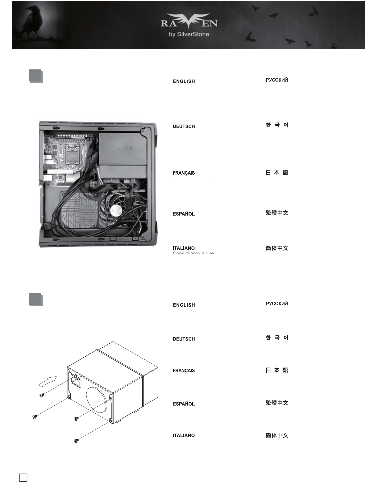
We recommend at this point connecting
all the necessary cables including the
SATA cables to the motherboard
Wir empfehlen, an diesem Punkt alle
erforderlichen Kabel, einschließlich
der SATA-Kabel, am Motherboard
anzuschließen
Nous vous recommandons à ce point
de brancher tous les cables nécessaires,
y compris les cables SATA, sur la carte
mère
Le recomendamos que en este punto
conecte todos los cables necesarios,
incluidos los cables SATA a la placa base
Consigliamo a questo punto di collegare
alla scheda madre tutti i cavi necessari
compresi i cavi SATA
Если вы собираетесь использовать
SilverStone NT06-PRO или аналогичную
систему охлаждения процессора,
переставьте 120-мм вентилятор сверхней
панели на нижнюю панель свентиляционными
отверстиями рядом сместом установки
графической картыA
SilverStone NT06-PRO 또는 기타 이와
유사한 CPU 쿨러를 사용하려는 경우 상단
패널의 120mm 팬을 그래픽 카드 근처에
있는 하단 통풍구로 위치를 바꾸십시오
將機殼所有線材連接上主機板,SATA線材建
議你這時可以先插上主機板
SilverStone NT06-PROまたはその 他同様
のCPUクーラーを使用される 場合は、ト
ップパネルの120mmファ ンをグラフィッ
クスカード付近の 底部換気口付近に移動
させます
将机箱所有线材连接上主板,SATA线材建议
你这时可以先插上主板
Wir
empf
ehle
n, a
n
e
r
f
orderlichen K
a
der
S
ATA-Kab
el
a
nz
usc
hli
eßen
Nous vous re
com
de brancher tous
le
y co
mpri
s les ca
ble
mè
r
e
Le recomenda
mos
c
onecte todos lo
s
incluidos los cables
Consigliamo a qu
es
Table des matières


