RAK RAK10701-P Manuel utilisateur
Documentation Center
RAK10701-P Field Tester Pro for LoRaWAN
Quick Start Guide
Prerequisites
What Do You Need?
Before going through each and every step in the installation guide of the RAK10701-P Field Tester Pro for
LoRaWAN, make sure to prepare the necessary items listed below:
Hardware Tools
1. RAK10701-P Field Tester Pro for LoRaWAN
2. LoRa SubGhz Antenna with RP-SMA connector
3. USB Type-C Cable
4. Windows/Linux/macOS for PC or iOS/Android for mobile
Software Tools
WisToolBox for configuration and firmware update.
📝
NOTE:
It is mandatory that you are within the coverage of the LoRaWAN Gateway of the network you are trying to
join. Without the coverage, the Field Tester will not be useable.
Product Configuration
RAK10701-P Field Tester Pro Physical Interface
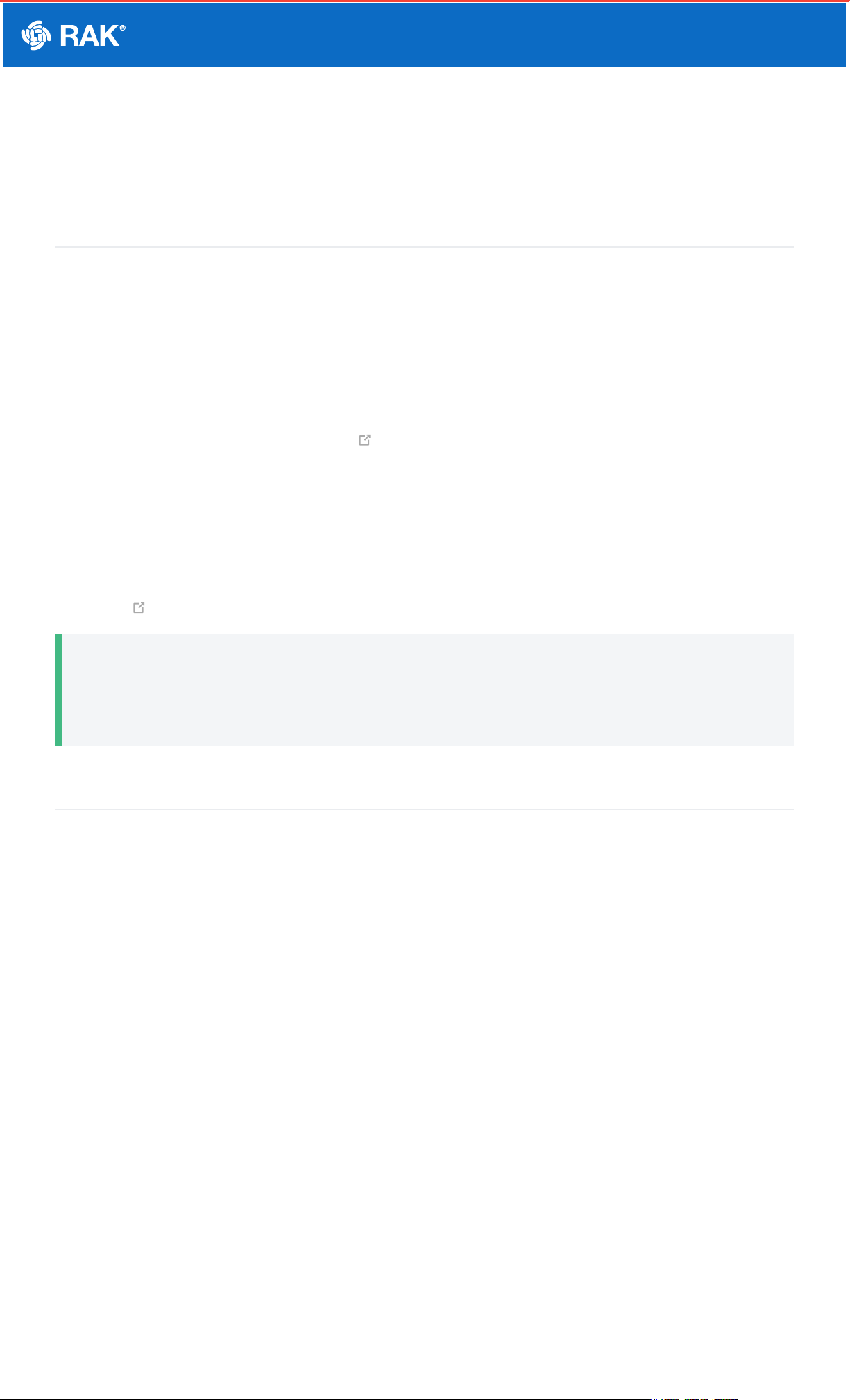
The user interface of the RAK10701-P Field Tester Pro for LoRaWAN is via TFT Touchscreen LCD and one
pushbutton at the side. There is also an external LoRA antenna port via RP-SMA connector and USB-C port for
charging and configuration if connected to a PC.
Documentation Center
Figure 1: Parts of RAK10701-P
📝
NOTE:
You have to ensure that the LoRa antenna is attached before turning on the device.
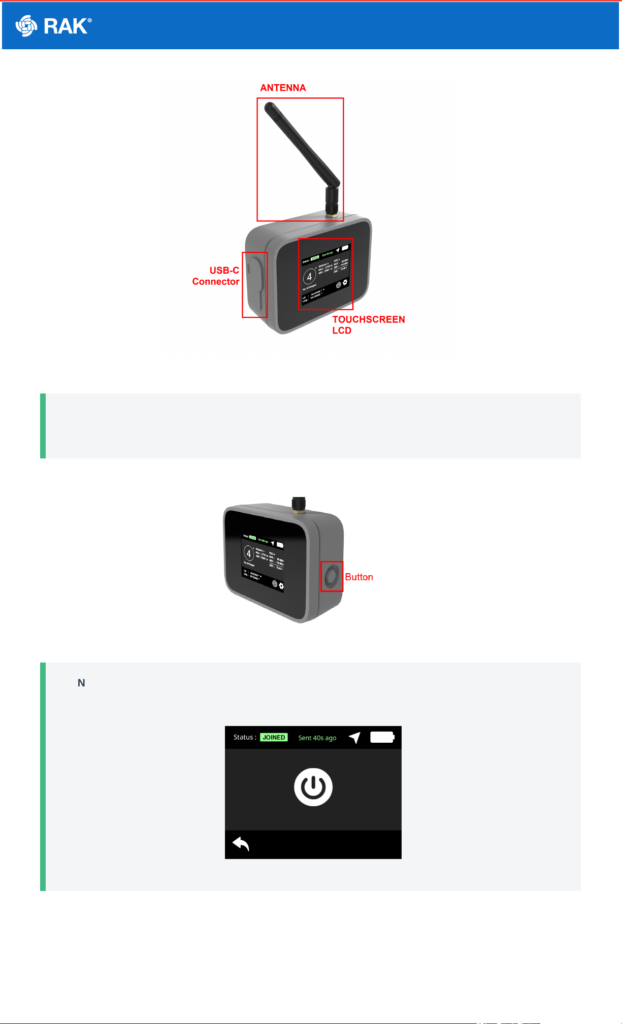
1. To turn on the device, you have to press and hold the button for at least five seconds.
Figure 2: RAK10701-P button to turn on
📝
NOTE:
The same button can be used to power off. You have to hold it as well for at least five seconds.
Figure 3: RAK10701-P power off
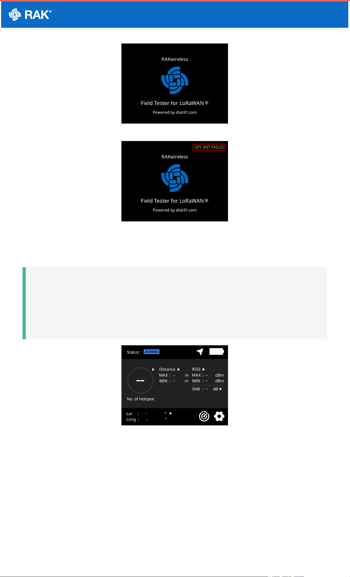
2. When the device initializes, it will show the RAK logo on the screen. If there is any initialization error, it will be
shown on the upper right section of the screen as well. A properly working device should not have any errors
shown.
Documentation Center
Figure 4: RAK10701-P power up successful
Figure 5: GPS error on boot up sequence
3. After the successful boot-up, the main home screen will be shown. Take note, that there will be no data at the
first start of the device.
📝
NOTE:
The field tester must be outside and has a clear view of the sky to get GPS coordinates. The GPS antenna
is located on top of the device beside the RP-SMA connector of the LoRa Antenna.
If you are indoors, there will be no reception of the GPS signal. The latitude and longitude data will be
empty.
Figure 6: RAK10701-P Main Page waiting for valid data
4. Once fully powered on, the external button at the side can sleep or wake up the display on the LCD screen via a
single press on it.
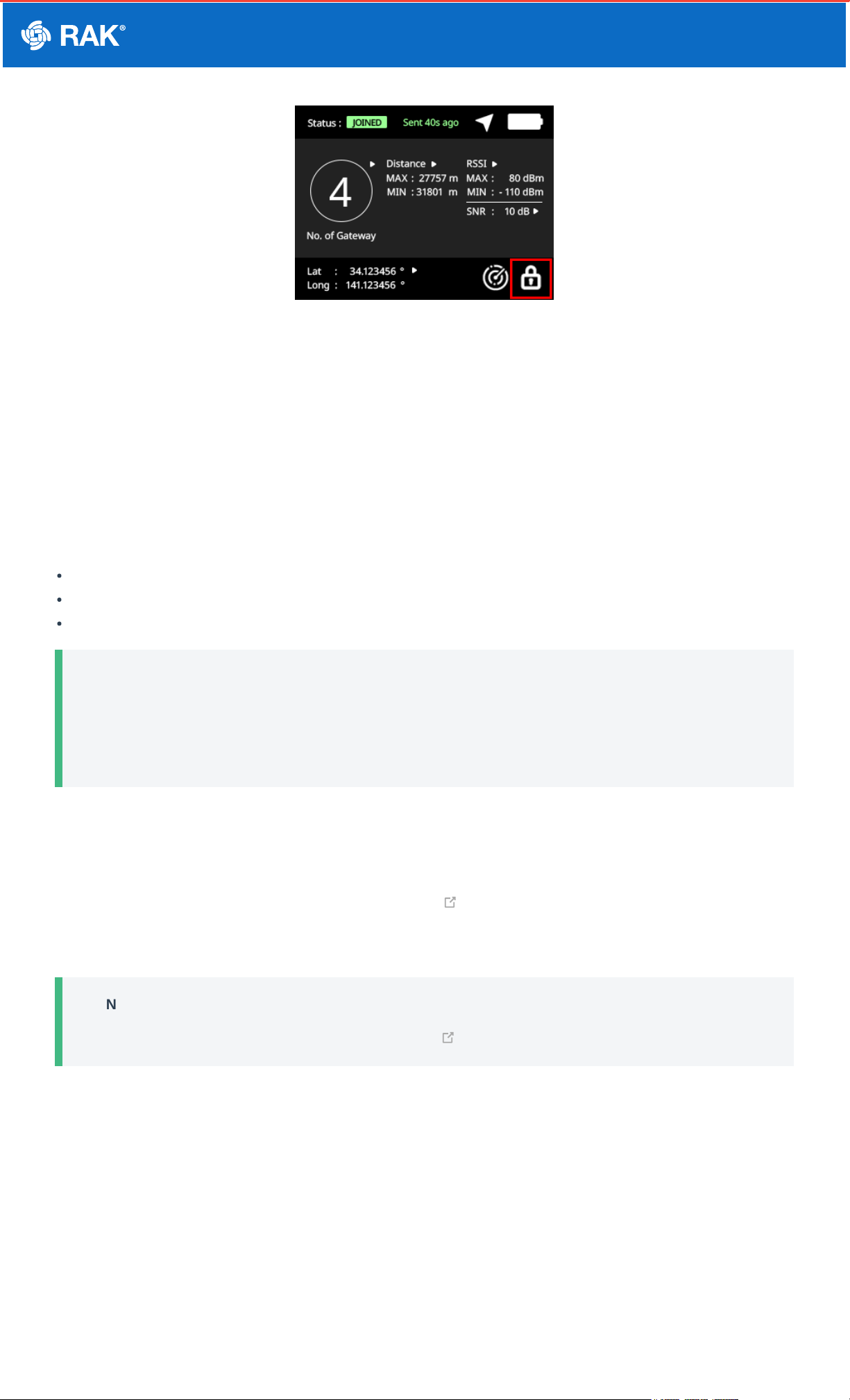
5. If the device is connected via USB-C to a computer, then the button is pressed, it will not remove the display but
will lock the screen (touch screen behavior is disabled).
Documentation Center
Figure 7: RAK10701-P locked screen
LoRaWAN Network Servers Guide for RAK10701-P
Field Tester Pro
The field tester supports different network servers and can be used as well on others not listed in this guide as
long as the uplink and downlink packets are configured correctly.
You can check each guide on how to use the RAK10701-P Field Tester Pro for LoRaWAN in the following network
servers.
Helium
The Things Network
Chirpstack (with Datacake integration used as backend)
📝
NOTE:
This section will focus on the configuration of each network server. The procedure of Device Configuration
of RAK10701-P via WisToolBox is the same for all network server and will be covered in a separate
section of the guide.
RAK10701-P Field Tester Pro Guide for the Helium
Network
RAK10701-P can be manually registered to Helium Console . This is a public LoRaWAN network server that
you can use for your LoRaWAN end-devices powered by community-driven Helium Hotspots. This guide will show
every detail of how to prepare the Helium Console for your RAK10701-P Field Tester Pro.
📝
NOTE:
This guide is based on disk19 guide for the Field Tester configuration for the Helium Console.
1. You need to register an account and then purchase data credits (DC) to use the network. If you are a new user,
there are free data credits (DC) included in your new account to get you started quickly.
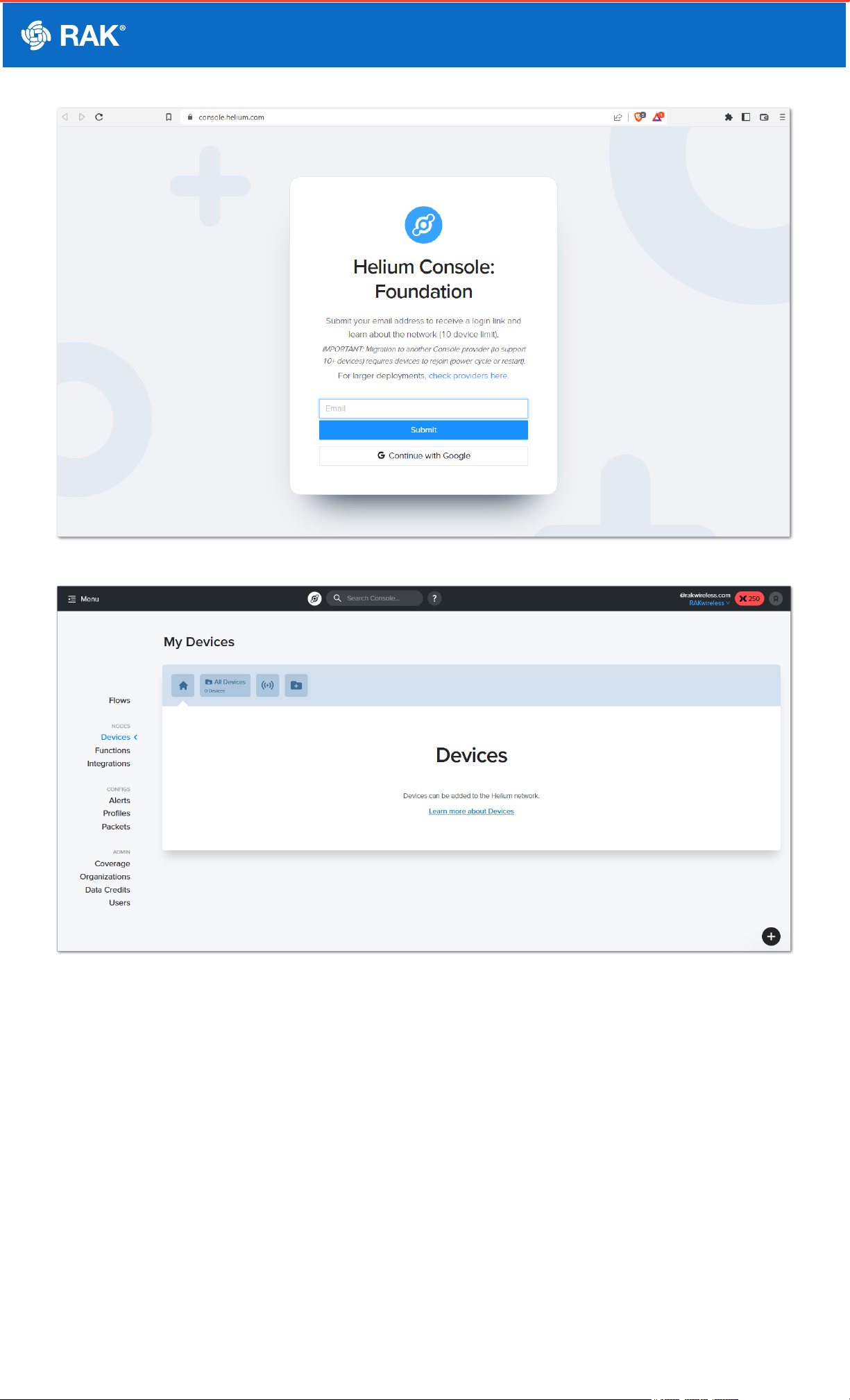
Documentation Center
Figure 8: Heluim Console
Figure 9: Console Home Page
2. Once you are logged in, you can start adding your device. You have two ways to add a device as shown in the
image.
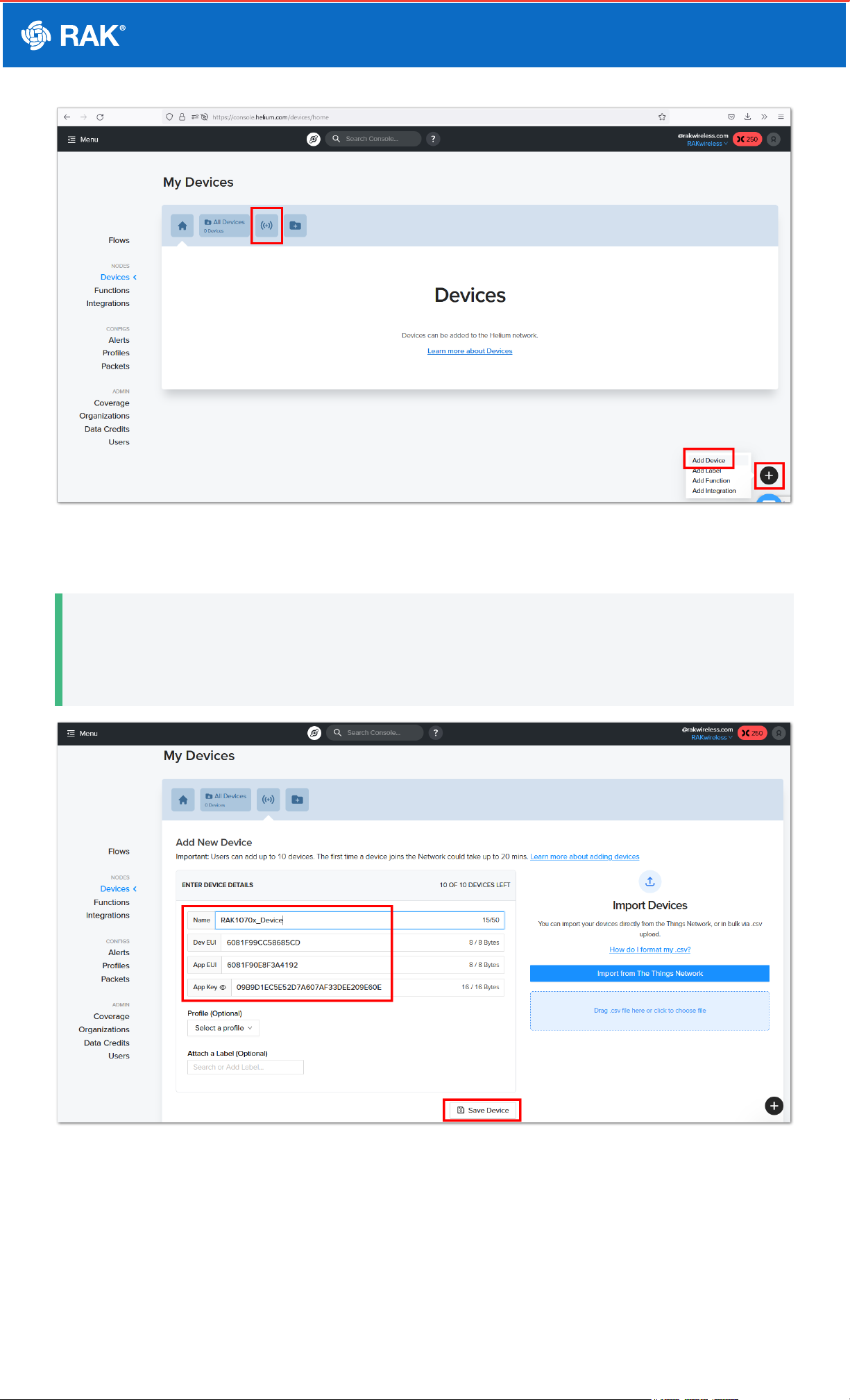
Documentation Center
Figure 10: Adding Device
3. The newly added device parameters will be shown. You have to put a device name and click save.
📝
NOTE:
The DEVEUI, APPEUI, and APPKEY are important in this step. These values must be configured on your
RAK10701-P device using WisToolBox which will be covered later in this guide.
Figure 11: Configuring Device Name
4. The device will be added to the blockchain and it will show pending beside its name.
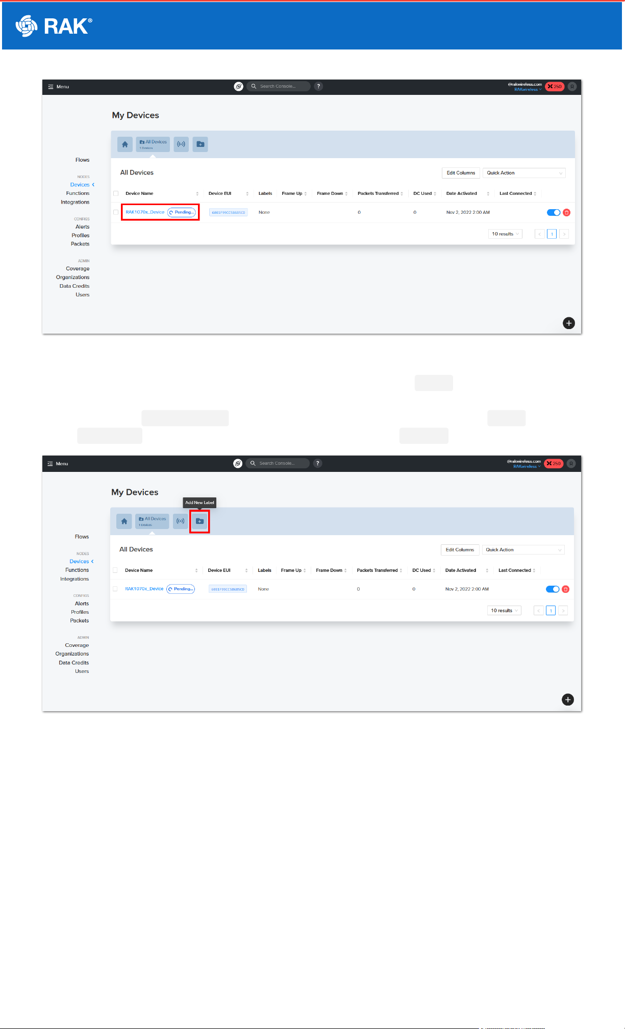
Documentation Center
Figure 12: Pending Device Status
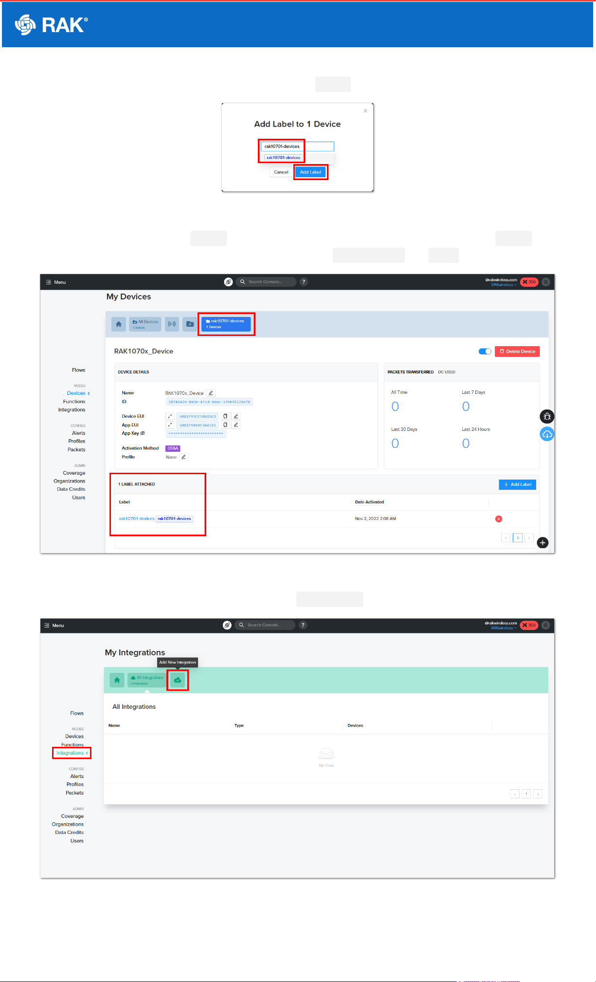
5. While waiting for the device to be added to the blockchain, you can create a Label . This will allow you to
group your device to have a common setting. This will be needed to attach the needed integrations to the
backend server of dev.disk91.com . You have to click the folder with the + icon and add a Label name then
click Save Label . The newly created label should now be shown in the Devices console.
Figure 13: Add Label icon
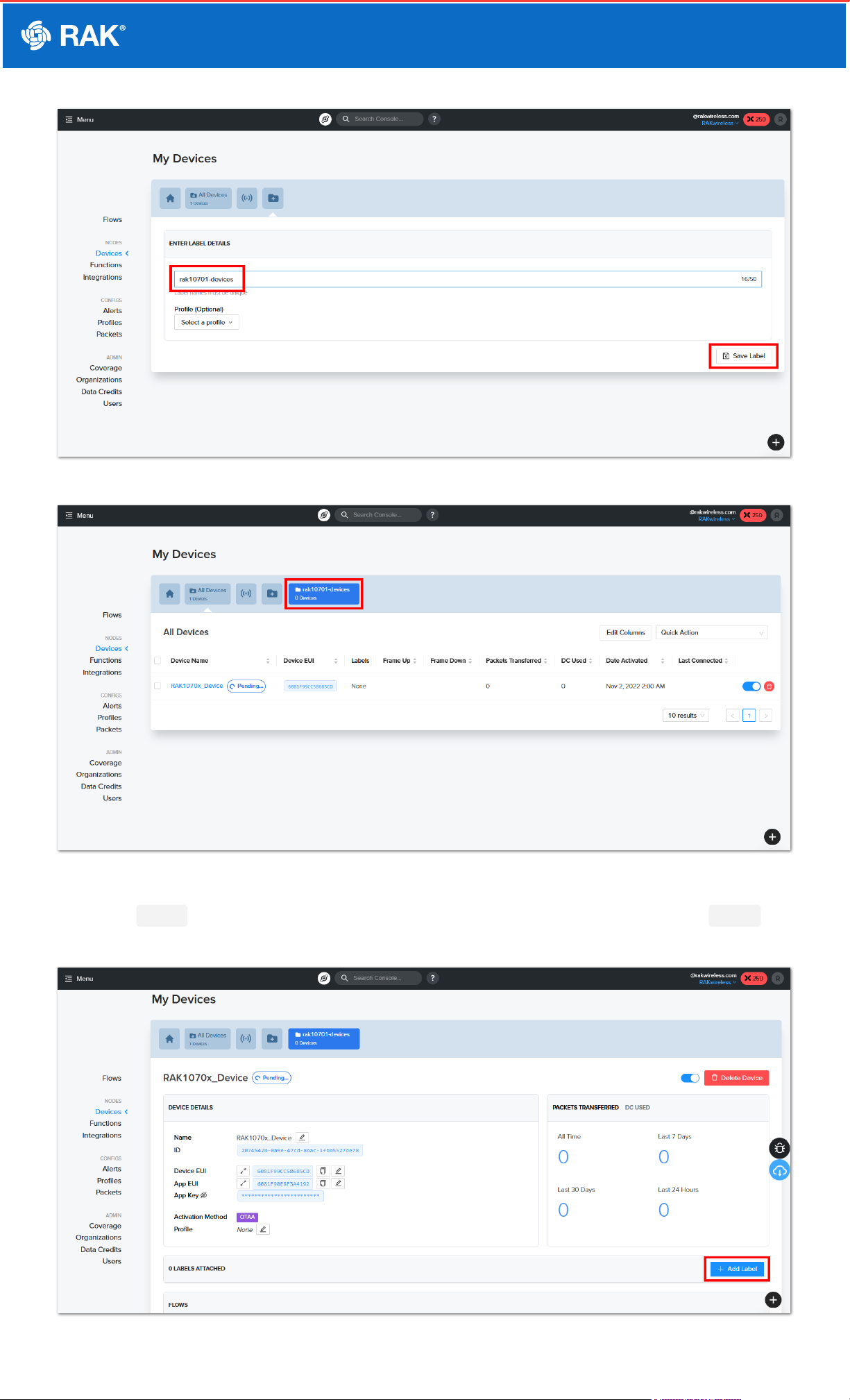
Documentation Center
Figure 14: Add Label Name
Figure 15: Label created successfully
6. Once the Label is created you have to associate it on the RAK10701 device. You can attach the Label on
the device by clicking the Add Label button.
Figure 16: Attach a label to the device
Documentation Center
7. A pop-up will be shown and you have to select the correct Label created for RAK10701 then click Add Label.
Figure 17: Drop-down on label selection
8. After successful attachment of Label on the devices, it should show one (1) device is under that Label . The
device is properly labeled which is needed for the next steps - Integrations and Flow .
Figure 18: Label added on the RAK10701 device
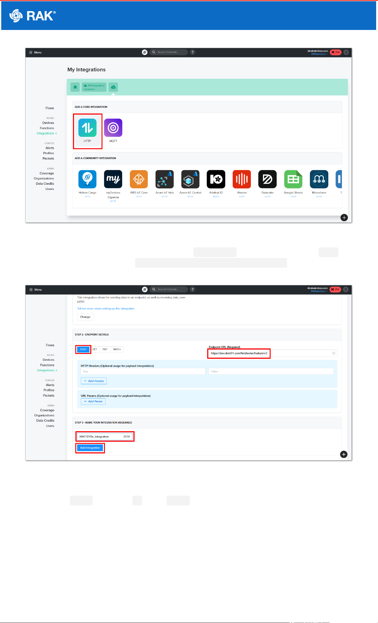
9. To connect the backend server, you have to create an Integration .
Figure 19: Add integration
Documentation Center
Figure 20: HTTP integration
10. Then you must proceed to steps 2 and 3 sections of the Integration settings. You have to select POST then
on the Endpoint URL, you must put https://dev.disk91.com/fieldtester/helium/v3 . It is also needed to
put the integration name before the clicking Add integration button.
Figure 21: Details of HTTP Integration
11. After preparing the device and the integration, you can now proceed with creating the flow to connect them. You
have to click Flows and then the + icon on NODES .
Table des matières
Manuels Équipement de test populaires d'autres marques

SMART
SMART KANAAD SBT XTREME 3G Series Manuel utilisateur

Agilent Technologies
Agilent Technologies BERT Serial Manuel utilisateur

Agilent Technologies
Agilent Technologies N3280A Manuel utilisateur

Vernier
Vernier Go Direct Voltage Manuel utilisateur

Lifeloc
Lifeloc R.A.D.A.R. Manuel utilisateur

Fluke
Fluke T5-600 Instructions d'utilisation et d'installation


