1.
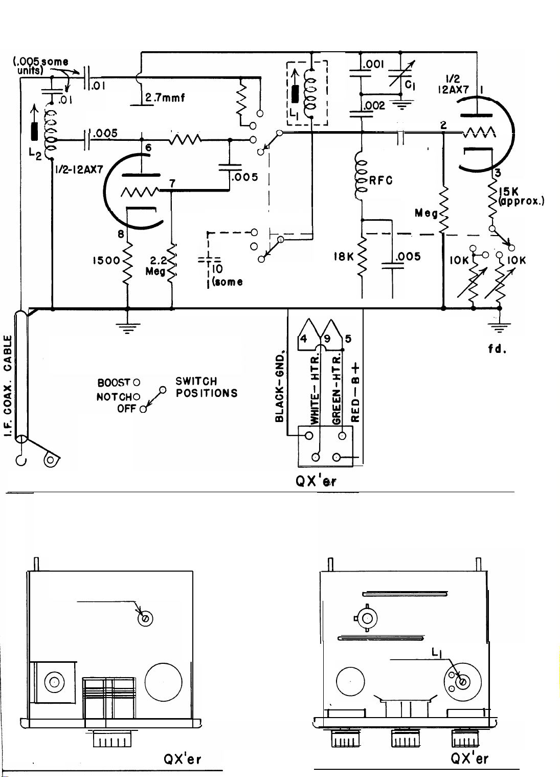
Connect power to the
Q-X’er
as follows:
Green wire to one side of
6.3
V. heater supply
White wire to other side of
6.3
V. heater supply
Note: Neither green nor white wire is grounded
in the
Q-X'er
so a
heater supply with cen-
ter tap ground or one side ground is 0. K.
Current required is
.3
amps.
Red wire to B-t 100 to 300 VDC
Current required is
.25
to 2 ma.
Black wire to Ground or B-.
.
2.
3.
4.
This
power can usually be taken from the accessory socket of the
receiver or slicer. The
Q-X’er
cable is supplied with a 4 pin
plug and socket
for
use when accessory socket is not available.
When a power or accessory socket is available, remove the 4 pin
plug which is supplied and replace it with one to match the acces-
sory socket. DO NOT connect coax cable yet.
Turn on receiver (if it has variable I. F. selectivity, set for most
tive position. If it has a crystal filter,leave it off. ) Carefully tune in and
center a steady carrier.
("S"
meter will show a peak.) DO NOT change
tuning again until
Q-X'er
is adjusted.
Slightly turn in each direction the adjusting screw on the 455 KC I. F. cir-
cuit to which the
Q-X'er
is to be connected to see that it is exactly peaked
to the rest of the set. This tuned circuit is preferably the one at the plate
of the mixer tube. Do not connect the
Q-X'er
to a low impedance point
such as the grid following a crystal filter or the plate or grid end of a
mechanical filter.
Connect the I. F. coax cable of the
Q-X'er
to the tuned circuit chosen above.
As stated, the mixer plate is ingeneral the best spot. If an octal based
tube is used, the connection can be made by removing the tube from the
socket, slipping the loop on the cable over the plate pin, and replacing the
tube in the socket. If a miniature tube is used, the coax connection should
be made by soldering directly to the socket under the chassis.
Connect
the coax direct; do not use a series condenser.
It should be noted here that there are three tuned
circuits involved in the operation: (1) in the I. F. trans-
former of the receiver,(2) the input coil of the
Q-X’er
which tunes out the capacity of the coax cable, and (3)
the
Q-X’er
tuning circuit. For proper operation it is
important that these three circuits be tuned to the same
frequency. Follow the installation instructions carefully.
II. INSTALLATION INSTRUCTIONS
selec
-
-2-