
Quantum FC420 Manuel utilisateur

Document 6473031-04, Ver. 4, Rel. 0, September 2003 1
Prism FC420 Bridge Option
User’s Guide
Introduction 3
Fibre Channel Overview ..........................................................................................4
Library Operation after Prism FC420 Bridge Installation ...................................4
Cabling the Library for Fibre Channel 4
One- and Two-Drive Library Cabling ....................................................................5
Cabling an ATL M2500 with Three or More Drives.............................................6
Setting SCSI IDs 10
Configuring FC420 Firmware 11
Setting up an Ethernet Connection .......................................................................11
Verifying Current FC420 Firmware......................................................................13
Scanning the SCSI Busses on the Library.............................................................14
Creating a Map File for the FC420 ........................................................................14
Making Other Configuration Changes.................................................................14
Restoring the PC to Its Original Configuration...................................................15
Prism FC420 Services Software Commands 15
Prism FC420 Service Software Operation ............................................................15
Command Syntax ....................................................................................................15
List of Abbreviations...............................................................................................16
Command Listing....................................................................................................16


Prism FC420 Bridge Option User’s Guide
Document 6473031-04, Ver. 4, Rel. 0
September 2003
Introduction 3
Introduction 0
This document explains how to configure and operate the FC420 Fibre
Channel bridge option installed in the Quantum ATL M-Series library.
For FC420 installation steps, refer to the FC420 Fibre Channel Bridge Quick
Reference Guide (PN 6473033).
For a description of ATL M-Series library operating procedures, see the
Quantum ATL M-Series Library User’s Guide (PN 6423002).
Figure 1 identifies the components of the FC420 bridge.
Figure 1 FC420 Bridge
Components
Note: If you do not have an MC300 Prism Management Card (PMC),
refer to Configuring FC420 Firmware to configure and
troubleshoot your FC420 bridge (or bridges).
Ready/Fault LED
Ethernet port
Activity LED for SCSI port 0
Activity LED for SCSI port 1
SCSI port 0
SCSI port 1
Fibre Channel speed LED
Fibre Channel activity LED
SFP Fibre Channel connector

Prism FC420 Bridge Option User’s Guide
Document 6473031-04, Ver. 4, Rel. 0
September 2003
4 Cabling the Library for Fibre Channel
Fibre Channel
Overview 0The Quantum ATL M-Series libraries are controlled by a host computer via an
LVD SCSI differential bus using the SCSI-2 medium changer command set.
The library’s Prism Architecture™ allows for easy conversion from the SCSI
host interface to a Fibre Channel host interface by installing the FC420 bridge
option.
Fibre Channel is a serial data transfer architecture for use with computers and
mass storage devices. Fibre Channel is rapidly emerging to challenge SCSI as
the interface of choice for host-to-storage applications.
Fibre Channel advantages include:
• Connection distances of up to 10 Kilometers
• Up to 2 Gb/sec data transfer rates with Auto-negotiate
• Support for up to 126 devices on a loop
• Support for 24-bit addressing for over 16 million devices in point-to-point
mode or fabric, when using a Fibre Channel switch or multiple Fibre
Channel switches
• Operating system independence
• Interconnect flexibility
• Fibre Channel fabric switches provide full direct connectivity between all
ports on a storage area network (SAN), which can increase the total
throughput of all devices on the SAN
Library Operation after
Prism FC420 Bridge
Installation 0
Once the Prism FC420 bridge SCSI to Fibre Channel option is installed and
tested, the library operates exactly as a library with a SCSI host interface. User
operation of the library via the graphical user interface (GUI) panel is
unchanged.
Cabling the Library for Fibre Channel 0
The cabling configuration used for the ATL M-Series library with the FC420
bridge option depends on the following factors:
• Number of tape drives installed
• Tape drive type (DLT8000, SDLT 220, SDLT 320, SDLT 600, HP LTO Gen
1, or HP LTO Gen 2)
• Number of FC420 bridges installed
• Data transfer rate of the storage area network (SAN)

Prism FC420 Bridge Option User’s Guide
Document 6473031-04, Ver. 4, Rel. 0
September 2003
Cabling the Library for Fibre Channel 5
One- and Two-Drive
Library Cabling 0If you are cabling an ATL M1500 library, or an ATL M2500 library with only
one or two tape drives, the cabling is the same regardless of drive type or
SAN. One- or two-drive libraries require only one FC420 bridge.
Figure 2 shows the cabling for a one-drive library.
Figure 2 One-Drive Library
Cabling
In a one-drive configuration (as shown in figure 2), a SCSI daisy chain is
established from one of the SCSI ports on the FC420 bridge to the SCSI
controller and then to drive 1, where the daisy chain is terminated. The SCSI
controller is included in the chain to pass SCSI commands to the robot.
The SCSI controller and drive 1 must be on the same SCSI bus because the
SCSI controller has termination disabled.
Note: HP LTO Gen 2 and SDLT 600 require 2 GB SAN connections. All
other drive types may have either a 1 GB or 2 GB SAN connection.
Drive 1
Slot for FC420
Slot for FC420
FC420
SCSI controller
SCSI
SCSI
SAN
Fibre
M1500 or M2500
Auxiliary
electronics
module
(M2500 only)
Primary
electronics
module
Terminator

Prism FC420 Bridge Option User’s Guide
Document 6473031-04, Ver. 4, Rel. 0
September 2003
6 Cabling the Library for Fibre Channel
Figure 3 shows typical cabling for a two-drive library.
Figure 3 Two-Drive Library
Cabling
In a two-drive library, the second drive (drive 2) should be connected to the
available FC420 port, creating a second SCSI bus. This utilizes the FC420
bridge fully and maximizes the communication bandwidth available to each
tape drive.
Cabling an ATL M2500
with Three or More
Drives 0
When cabling an ATL M2500 with three or more tape drives, you need to
know the type of tape drive installed in the library and the data transfer rate
of the SAN to determine the correct SCSI configuration.
To cable a library with:
• SDLT 220, SDLT 320, or HP LTO Gen 1 drives, refer to SDLT 220, SDLT
320, or HP LTO Gen 1 Drive Cabling with a 1 Gb SAN or SDLT 220, SDLT
320, or HP LTO Gen 1 Drive Cabling with a 2 Gb SAN
• SDLT 600 or HP LTO Gen 2 drives, see SDLT 600 or HP LTO Gen 2 Drive
Cabling
• DLT8000 drives, see DLT8000 Drive Cabling
Note: As with the one- and two-drive configurations, all Fibre-to-SCSI
cabling configurations must include the SCSI controller so that
SCSI commands intended for the robot are communicated
successfully.
Drive 2 Drive 1
Slot for FC420
Slot for FC420
FC420
SCSI controller
SCSI
SCSI
SCSI
SAN
Fibre
M1500 or M2500
Auxiliary
electronics
module
(M2500 only)
Primary
electronics
module
Terminator
Prism FC420 Bridge Option User’s Guide
Document 6473031-04, Ver. 4, Rel. 0
September 2003
Cabling the Library for Fibre Channel 7
SDLT 220, SDLT 320, or HP LTO Gen 1 Drive Cabling with a 1 Gb SAN 0
If an ATL M2500 containing SDLT 220, SDLT 320, or HP LTO Gen 1 drives is
connected to a 1 Gb SAN, a ratio of one tape drive per FC420 SCSI port is
recommended. This means that three- and four-drive libraries require a
second FC420 bridge, and five- and six-drive libraries require three FC420
bridges, as shown in figure 4.
Figure 4 One-Drive-Per-
FC420-Port Cabling
SDLT 220, SDLT 320, or HP LTO Gen 1 Drive Cabling with a 2 Gb SAN 0
If an ATL M2500 containing SDLT 220, SDLT 320, or HP LTO Gen 1 drives is
connected to a 2 Gb SAN, a maximum ratio of two tape drives per FC420 SCSI
port is recommended. This means that one FC420 bridge could manage up to
four tape drives, but a second FC420 bridge is required for libraries with five
or six tape drives.
Note: SDLT and LTO tape drives are sometimes referred to as
Superdrives.
Drive 2 Drive 1
Drive 4 Drive 3
Drive 6 Drive 5
FC420
FC420
FC420
SCSI controller
SCSI
SCSI
SCSI
1 Gb SAN
Fibre
Primary
electronics
module
Auxiliary
electronics
module
M2500
SCSI SCSI
SCSI
SCSI
Fibre
Fibre
Terminator

Prism FC420 Bridge Option User’s Guide
Document 6473031-04, Ver. 4, Rel. 0
September 2003
8 Cabling the Library for Fibre Channel
Figure 5 shows a six-drive library utilizing a two-drive per SCSI port cabling
scheme.
Figure 5 Two-Drive-per-
FC420-Port Cabling
Note: To increase the bandwidth available to each tape drive, install
additional FC420 bridges and use the cabling configuration shown
in figure 4.
Drive 2 Drive 1
Drive 4 Drive 3
Drive 6 Drive 5
Slot for FC420
FC420
FC420
SCSI controller
SCSI
SCSI
SCSI
SCSI
2 Gb SAN
Fibre
Primary
electronics
module
Auxiliary
electronics
module
M2500
SCSI SCSI
Fibre
SCSI
Terminator

Prism FC420 Bridge Option User’s Guide
Document 6473031-04, Ver. 4, Rel. 0
September 2003
Cabling the Library for Fibre Channel 9
SDLT 600 or HP LTO Gen 2 Drive Cabling 0
SDLT 600 and HP LTO Gen 2 drives can only be used with a 2 Gb SAN. A
ratio of one tape drive per FC420 SCSI port is recommended. This means that
three- and four-drive libraries require a second FC420 bridge, and five- and
six-drive libraries require three FC420 bridges, as shown in figure 6.
Figure 6 SDLT 600 or HP
LTO Gen 2 Drive Cabling
Drive 2 Drive 1
Drive 4 Drive 3
Drive 6 Drive 5
FC420
FC420
FC420
SCSI controller
SCSI
SCSI
SCSI
2 Gb SAN
Fibre
Primary
electronics
module
Auxiliary
electronics
module
M2500
SCSI SCSI
SCSI
SCSI
Fibre
Fibre
Terminator

Prism FC420 Bridge Option User’s Guide
Document 6473031-04, Ver. 4, Rel. 0
September 2003
10 Setting SCSI IDs
DLT8000 Drive Cabling 0
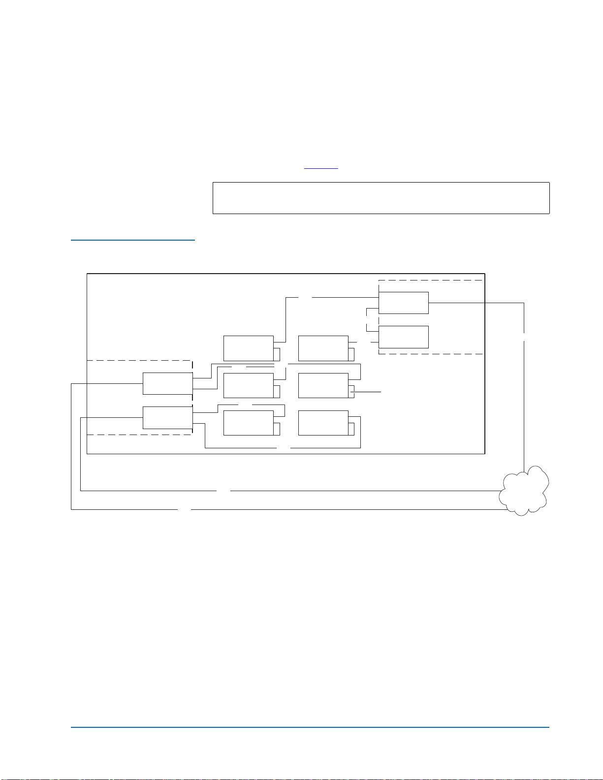
A single FC420 bridge installed in an ATL M2500 library with DLT8000 tape
drives can manage up to four drives per SCSI port. Figure 7 shows a typical
cabling configuration, with the SCSI controller and three drives on one SCSI
bus, and three drives on the other SCSI bus.
Figure 7 DLT8000 Drive
Cabling
Setting SCSI IDs 0
Use the information in table 1 to set the SCSI device addressing (SCSI IDs) for
the library.
Table 1 SCSI ID Settings
Note: To increase the bandwidth available to each drive, install
additional FC420 bridges and use the cabling configuration shown
in figure 4 or in figure 5.
Device SCSI ID Device SCSI ID
SCSI Controller 0 Drive 4 4
Drive 1 1 Drive 5 15
Drive 2 2 Drive 6 14
Drive 3 3
Drive 2 Drive 1
Drive 4 Drive 3
Drive 6 Drive 5
Slot for FC420
Slot for FC420
FC420
SCSI controller
SCSI
SCSI
SCSI
SCSI
SCSI
SCSI
SCSI
SAN
Fibre
M2500
Auxiliary
electronics
module
Primary
electronics
module
Terminator
Autres manuels pour FC420
1
Table des matières


