Pumpex P 601 Manuel d'utilisation original
P 601 - P 3001
SERVICE INSTRUcTION
SERVICE INSTRUCTION
P 601 - P 3001
P 601/701/801/1001/1501/2001/3001.58.0308.Eng/Digital
2 (22)
Pump- 3-fas 1-fas
modell
220 V 346-500 V 110 V 220V
P 601 10 A 6 A 16 A 10 A
P 701 10 A 6 A 16 A 10 A
P 801 16 A 10 A
P 1001 16 A 10 A 16 A
P 1501 25 A 16 A
P 2001 25 A 16 A
P 3001 63 A 35 A
These Service Instructions apply to PUMPEX electric submersible
drainage pump models P 601-701-801-1001-1501-2001 and 3001.
All configurations; including, centerline, high volume, normal head,
and high head.
Pump models P601 P 701 and P 1001 and P 2001 are available in
either 3-phase or single-phase operation; other models for 3-phase
operation only. All pumps for 3-phase operation are equipped for
D.O.L. start, and do not require an external start control. Model P
2001W is equipped as 230v 1-phase, and is supplied with a factory
control box. Only a factory supplied control box should be used on
this pump.
All 3-phase pumps are fitted with a built-in contactor unit and thermal
switches in the stator windings, connected in series with the contactor
coil. Single phase pumps have start capacitors or factory supplied
control box. In case of the motor overheating, the thermal switches
open and disconnect the contactor and the power supply to the pump.
Note!! When the motor has cooled down the thermal switches close
and re-start the pump automatically.
Connection at the job site
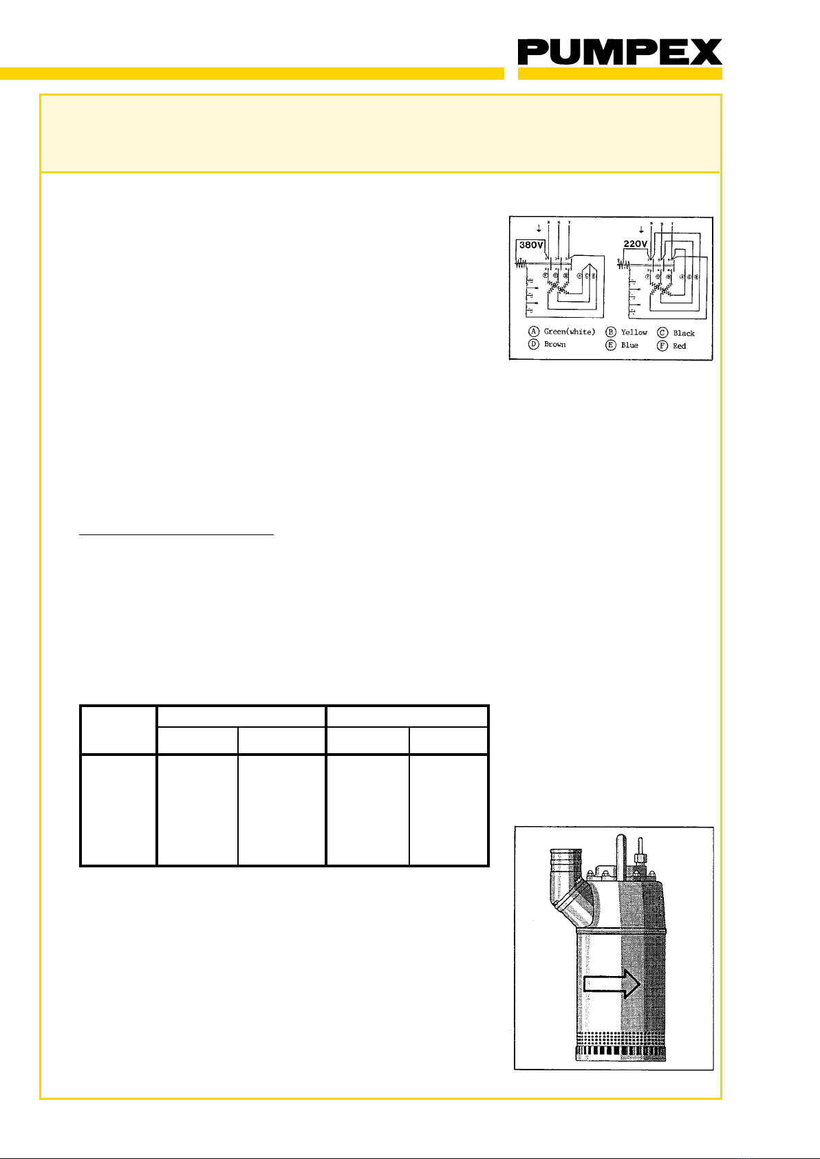
Check that the pump is connected for the actual mains voltage.
Reconnection between 230 volts and 460 volt 3-phase is made by
changing the contactor coil and reconnect according to the wiring
diagram.
If the contactor is not equipped with a dual voltage contactor coil, the
coil must be replaced to coincide with the desired voltage at the site.
Separate external motor protector is not required, but fuses of correct
size should be installed as short-circuit protection. Use time lag fuses
according to the following table.
Check the direction of rotation in all 3-phase pumps. Tilt the pump and
start it. It should jerk in a counter clockwise direction as indiciated by
an arrow on the pump. If it jerks in the other direction, two phases
should be shifted. If the bottom of the sump is soft and muddy, place
the pump on some planks, put it into a bucket, or suspend it from a
rope to prevent it from digging itself into the mud.
Never lift or pull the pump by the electric cable. Note!! Harm to the
pump cable may cause injury or death.
Always disconnect the pump from the power supply before opening
any part of the pump. Always use a qualified electrical technician
when servicing pump.
SERVICE INSTRUCTION
P 601 - P 3001
P 601/701/801/1001/1501/2001/3001.58.0308.Eng/Digital
3 (22)
If the seals are worn so severely that the oil has leaked out and only
water mixed with mud and sand remains, the pump must be dis-
mantled for a complete overhaul.
Maintenance
Inspection at regular intervals and preventive maintenance should be
performed in order to reduce the number of functional troubles and to
avoid serious break-down of the pump unit. During normal opera-tion
service is not required until a reduction of the pump capacity is noted.
Inspection must be performed once a year, or 2000 operating hours.
When the pump is taken out of service for seasonal storage, a full
maintenance service should be carried out. Special attention should
be paid to the following points.
Cleaning and Removal of Lime Deposits
At a construction site the pump is often working in water mixed with
clay, concrete, lime, etc. When it is taken out of service it should be
flushed out in fresh water and fully inspected before it is put into
storage.
Hard and solid lime deposits are easily removed if the pump is fully
submersed in a vessel with a mixture of one part formic acid (HCOOH)
and 15 parts water.
Remove the pump after 5 minutes and flush it in fresh water. Some
deposits may remain, and a second treatment may be necessary. Not
all deposits may be removed.
Inspection of Shaft Seals
Check the condition of the shaft seal by inspection of the oil in the oil
chamber. Proceed as follows:
Remove base plate and outer casing. If it is difficult to remove the
casing due to deposits or build-up on the inside, the diffuser can be
removed together with the casing.
Unscrew the oil plug and drain the oil into a clean can and inspect it.
If the oil is clean and contains no water, the primary seal is free from
defects and can be used again. If the oil contains water and appears
”milky”, the seals must be changed and ball bearings checked. After
inspection and possible change of shaft seals new oil should be filled
into the oil chamber.
Oil type: Oil type: White oil with a viscosity of 10-15cSt, such as BP
Enerpar M 002 or equivalent.
Oil quantity: P 601 0.35
P 801 0.35
P 701 0.50
P 1001 0.50
P 1501 0.50
P 2001 0.90
P 3001 0.90
Replace inspection plug O-ring
SERVICE INSTRUCTION
P 601 - P 3001
P 601/701/801/1001/1501/2001/3001.58.0308.Eng/Digital
4 (22)
Inspection of Hydraulic Parts
Remove the diffuser, and check the rubber coating for wear, missing
or heavly scored material, and deposits.
Minor wear is easily compensated by tightening the nuts for the
diffuser thus reducing the clearance from the impeller to .0004 in.
Replace diffuser and wear plate if the rubber coating is worn to the
point where the metal backing is showing, or if any pieces of rubber
material are missing or severly gouged.
Inspection of electric cable
Check that the cable is undamaged, if the outer sheath is damaged,
water may wick into the motor housing along the inner core. If the
cable is damaged, repair or replace. Also check that the cable has
not been stretched or deformed. Hard jerks or pulls on the cable may
have damaged the bushing in the cable gland.
Trouble shooting
The most frequent functional troubles are usually caused by improper
electrical installation, cables, or wiring connections. Always have
pumps installed by a qualified electrician. A volt ohm meter and valid
wiring diagram for the correct voltage are required in order to trouble-
shoot the electrical portion of the equipment.
All troubleshooting should be carried out with the equipment
disconnected from the electric power supply. The power supply
must be locked out when performing routine maintenance, or
troubleshooting pump. Always check that no other person is working
with the pump before connecting the pump to power supply and
energizing the pump. All work with the electrical installation must be
carried out by a qualified electrician, or under the supervision of an
authorized electrician.
A. The pump will not start.
May be caused by:
1. Dead incoming power lines.
2. Blown fuses or breakers.
3. Defective cable.
4. Defective contactor unit or burned motor
5. Blocked impeller
B. The motor trips out.
May be caused by:
1. Wrong direction of rotation
2. Pump overloaded due to material build up.
3. Excessive water temperature. (Max 105 F)
4. Impeller blocked by stones, pieces of wood.
5. Blocked rotor.
6. Low voltage due to long cables, or inadequate power supply
(generator).
7. Phase failure.
8. Burned motor caused by water entering pump either through shat
seal or cable entry area.

SERVICE INSTRUCTION
P 601 - P 3001
P 601/701/801/1001/1501/2001/3001.58.0308.Eng/Digital
5 (22)
C. Water inside top cover, and /or main cover
May be caused by:
1. Pump cable damaged or cut permitting water to penetrate into top
of pump
2. Loose cable gland or faulty assembly of gland.
3. Damaged 0-ring , foreign matter between motor housing and main
cover, or top cover
4. Wire(s) pinched between top cover and main cover.
5. Loose or missing nuts that secure top cover to main cover.
D. Pump operating at too low capacity
May be caused by:
1. Wrong direction of rotation.
2. Worn or damaged impeller and / or diffuser.
3. Clogged strainer.
4. Sharp bends, folds or restrictions
of the discharge hose.
5. Total Delivery Head (static head + friction losses) too high
E. Water-in-the-oil-chamber
May be caused by:
1. Defective shaft seal
2. Faulty assembly of 0-rings, mechanical seal, wear plate or
SERVICE INSTRUCTION
P 601 - P 3001
P 601/701/801/1001/1501/2001/3001.58.0308.Eng/Digital
6 (22)
Complete overhaul
A complete overhaul of the pump should be carried out if there has
been water or oil in the motor housing, or if the pump has been in daily
operation for one year or 2000 operating hours. At low utilization the
pumps overhaul intervals can be extended.
Dismantle the pump completely, replace damaged and worn parts.
Clean all sealing surfaces and check that they are not damaged. If
water or oil has leaked into the motor housing, inspect and replace
ball bearings and shaft seals as required.
Warning
Prior to any work being carried out, always check that the pump is
disconnected from the power supply, and cannot be energized.
Dismantling
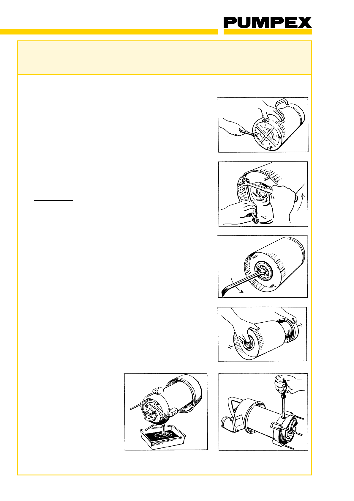
Loosen the bottom nuts/screws and remove the base plate. Unscrew
the nuts for the diffuser. Remove outer casing and diffuser with a crow
bar applied between diffuser and impeller nut. Pull out the diffuser
from the outer casing.
Unscrew the oil plug and drain the oil into a clean can and inspect it.
Check the oil. See maintenance of Shaft Seals.
SERVICE INSTRUCTION
P 601 - P 3001
P 601/701/801/1001/1501/2001/3001.58.0308.Eng/Digital
7 (22)
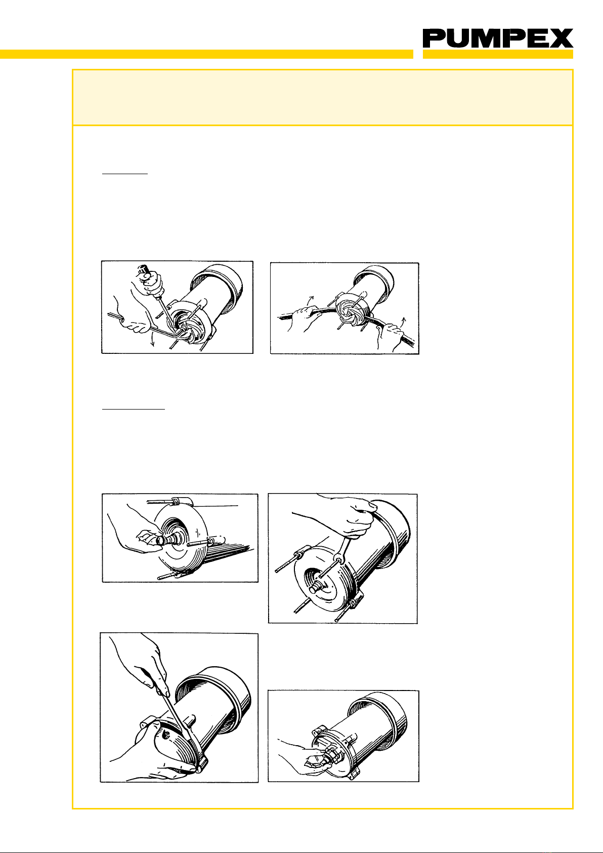
Impeller
Remove the rubber covers from the stud bolts. Hold the impeller with
a large screwdriver or similar between the vanes and unscrew the
impeller nut with an 8 mm Allen key.
Prize the impeller loose with two screwdrivers under the impeller hub.
Remove the key from the shaft. Replace if damaged.
Shaft Seals
Pull out the rotating ring of the primary seal with sleeve and spring and
remove the 0-ring from the shaft.
Unscrew the stud bolts. Withdraw the wear plate and remove the
stationary ring of the primary seal.

SERVICE INSTRUCTION
P 601 - P 3001
P 601/701/801/1001/1501/2001/3001.58.0308.Eng/Digital
8 (22)
Cut the lock washer part No. 00471 with a pair of nippers. Pull out the
lock washer carefully in order to avoid scratching the shaft. Remove
any possible scratches before pulling out the rotating part of the
secondary shaft seal. Screw puller part No. 00470 into the stationary
ring of secondary seal and pull out the ring.
Rotor Unit
Unscrew the screws which hold stator housing and oil casing together.
Turn the housing about 15oand prize it loose from the casing with a
screwdriver. Remove the stator unit.
SERVICE INSTRUCTION
P 601 - P 3001
P 601/701/801/1001/1501/2001/3001.58.0308.Eng/Digital
9 (22)
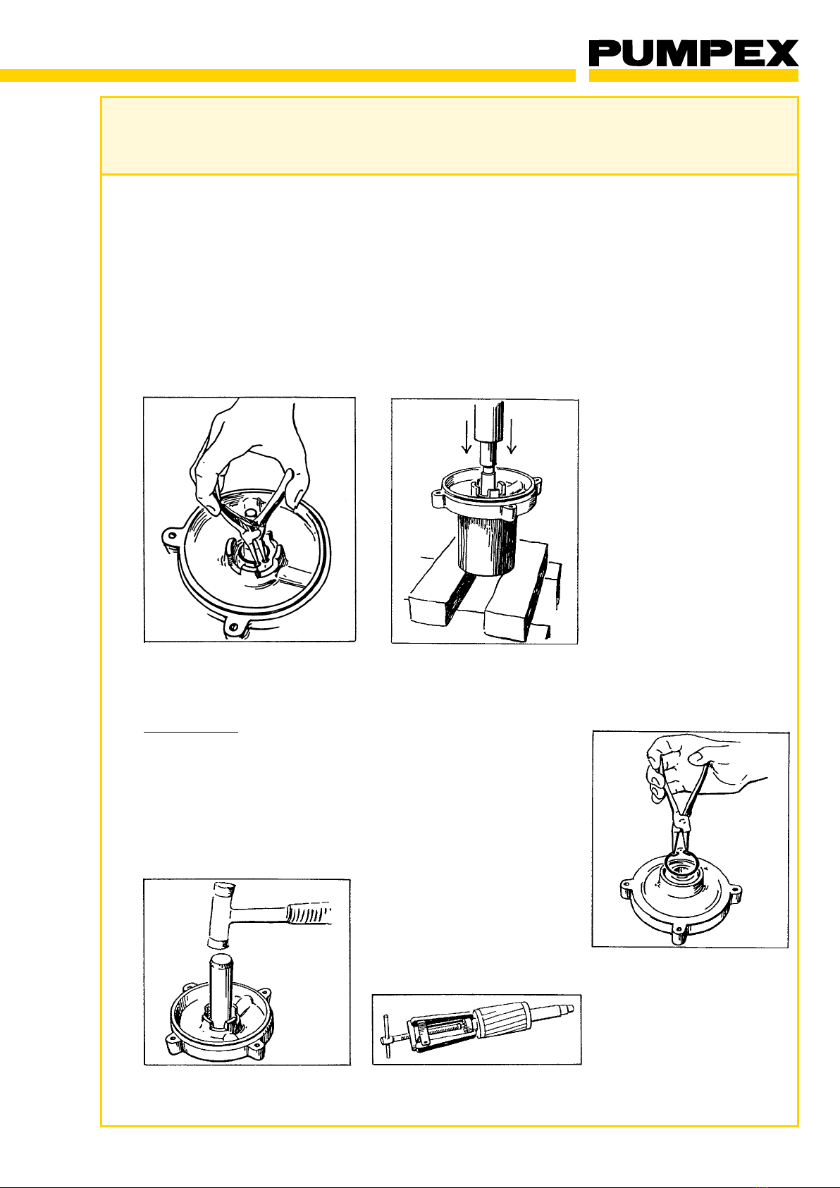
Remove the external circlip on the shaft (inside secondary seal) with
a pair of circlip pliers for Dia. 25 mm.
The rotor shaft has to be pressed out of the ball bearing. Put the rotor
into a tube of the same length as the rotor shaft and with an inner dia-
meter slightly larger than the outer diameter of the bearing seat.
Press against the end of the shaft until the rotor comes loose. If a
high pressure is needed, screw the impeller nut fully on the shaft end
in order to protect it.
Ball Bearing
Remove the internal circlip and Nilos ring for the ball bearing and
press out the bearing. If necessary, the bearing seat can be heated
quickly with LP-gas to facilitate the removal.
Remove the washer and circlip in the bottom of the bearing seat. Pull
out the upper ball bearing with a puller.
SERVICE INSTRUCTION
P 601 - P 3001
P 601/701/801/1001/1501/2001/3001.58.0308.Eng/Digital
10 (22)
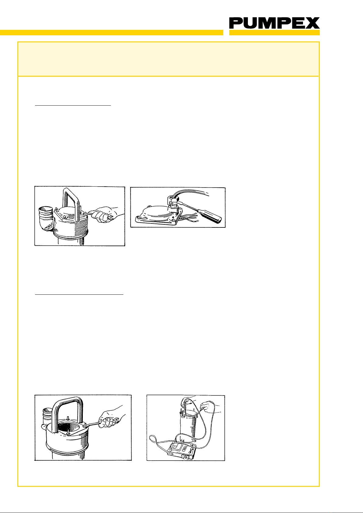
Cover and Cable Gland
Unscrew the cap nuts for the cover. Lift off the cover and disconnect
the cable from the contactor (3-phase units only).
If water has penetrated through the cable gland, the cable seal should
be replaced. Remove strain relief clamp prior to unscrewing cable
gland body. Pull out cable, rubber bushing and washers.
NOTE!! It is very important that the replacement parts be correctly
sized for the cable. Incorrect sizing can cause severe damage to the
pump.
Stator Unit with Contactor
Unscrew the nuts for main cover and remove the main cover from the
stator unit.
The motor insulation should always be tested in connection with
service or repair. Measure insulation resistance between the different
phase windings, between windings and ground, and between win-
dings and thermal switch circuit. The insulation resistance should be
measured with 500 V megohm-meter, and the reading should be at
least I megaohm. If the reading is lower, but not completely open,
drying the stator may recover usage of the motor.
If insulation resistance test shows motor open, the stator unit should
be rewound, or replaced.
Ce manuel convient aux modèles suivants
6
Table des matières
Autres manuels Pumpex Pompe à eau

Pumpex
Pumpex P 401 Comment utiliser

Pumpex
Pumpex K 101 Manuel d'utilisation original

Pumpex
Pumpex KG 30 Manuel utilisateur

Pumpex
Pumpex K 80 Comment utiliser

Pumpex
Pumpex KV 30 Comment utiliser

Pumpex
Pumpex K 82 Manuel d'utilisation original

Pumpex
Pumpex K 60 Comment utiliser

Pumpex
Pumpex K 107 Comment utiliser

Pumpex
Pumpex K 152 Mode d'emploi
Manuels Pompe à eau populaires d'autres marques


Sykes AmeriPumps
Sykes AmeriPumps GP100M Guide de dépannage

DUROMAX
DUROMAX XP WX Series Manuel utilisateur

BRINKMANN PUMPS
BRINKMANN PUMPS SBF550 Manuel utilisateur

Franklin Electric
Franklin Electric IPS Manuel utilisateur

Xylem
Xylem e-1532 Series Manuel utilisateur

Milton Roy
Milton Roy PRIMEROYAL Manuel utilisateur