Promax AC-726 Manuel utilisateur

SAFETY RULES
Safety Instructions
During each stage of operation of this instrument, please always observe the
following safety instructions. Not taking any safety precautions or following the
instructions will violate the safety standards of design, manufacturing and
application of these instruments. In no case will PROMAX bear the responsibilities
for consequences incurred by violation of the following instructions.
General
This product is a Safety Class 1 instrument. The protective features of this
product may be impaired if it is used in a manner not specified in the operation
instrument.
Environmental conditions
It is designed to operate at a maximum relative humidity of 95% and at altitudes
of up to 2000 meters. Refer to the specifications tables.
Before applying power
Verify that the product is set to match the available line voltage, the correct fuse
is installed, and all safety precautions are taken. Note the instrument’s external
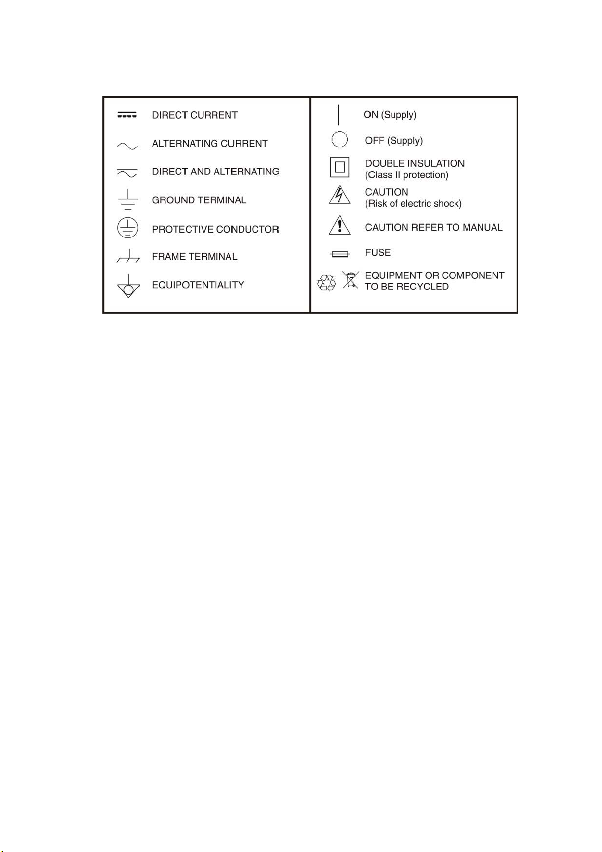
markings described under Symbols.
Do not operate in an explosive atmosphere
Do not operate the instrument in the presence of flammable gases or fumes.
Do not remove the instrument cover
Operating personnel must not remove instrument covers. Component replacement
and internal adjustments must be made only by qualified service personnel.
Instrument that appears damaged or defective should be made inoperative and
secured against unintended operation until they can be repaired by qualified
service personnel.
Electrical safety precautions
If you need to ensure that the equipment completely off, unplug the power line
and remove the battery.
Warning
Only using the AC/DC power adapter in the room.
The equipment should be placed where the surrounding air can flow freely.
Do not operate equipment in the flammable gas or near the smoke.
Do not operate equipment if any part of outer surface (upper cover panel, etc.)
damaged, To avoid the electric shock.
Only approved professional personnel can open and debug and maintenance or
repair the equipment when its power supply is turned on.
Even turn off the power supply, equipment still be in a charged state over a
period of time due to internal capacitor.

* Symbols related with safety:
Descriptive Examples of Over-Voltage Categories
Cat I Low voltage installations isolated from the mains.
Cat II Portable domestic installations.
Cat III Fixed domestic installations.
Cat IV Industrial installations.

TABLE OF CONTENTS
1 GENERAL INFORMATION...................................................................... 5
1.1 Scope of this information................................................................ 5
1.2 Unpacking and Inspection............................................................... 5
1.3 Product Introduction ...................................................................... 5
2 THE APPEARANCE INTRODUCTION OF EQUIPMENT..............................6
2.1 The head cover ............................................................................. 6
2.2 Front panel................................................................................... 7
3 USER INTERFACE AND MENU INSTRUCTIONS ......................................9
3.1 Turn on the instrument .................................................................. 9
3.2 Main interface............................................................................. 10
3.3 Measurement Interface ................................................................ 11
3.4 The function menu description ...................................................... 13
3.4.1 Marker .................................................................................... 13
3.4.2 Limit Line ................................................................................ 15
3.4.3 Scale....................................................................................... 17
3.4.4 File ......................................................................................... 18
3.4.5 Display.................................................................................... 21
3.4.6 Average/Smooth....................................................................... 23
3.5 Calibration interface .................................................................... 24
3.6 System Settings Interface ............................................................ 26
3.7 Help Interface............................................................................. 31
4 COMMON OPERATING INSTRUCTIONS ............................................... 34
4.1 Set frequency parameter.............................................................. 34
4.2 Set DTF parameter ...................................................................... 36
4.2.1 Set Distance parameter ............................................................. 37
4.2.2 Set Cable parameter ................................................................. 38
4.2.3 Set Window Function ................................................................. 39
4.3 OSL Calibratrion.......................................................................... 39
4.4 Freq-Return Loss, Freq-VSWR, Cable-Loss measurement .................. 40
4.5 DTF-VSWR, DTF-Return Loss measurement .................................... 41
5 AC-726 PERFORMANCE....................................................................... 42

5 April 2016
CABLE AND ANTENNA ANALYSER
AC-726
1 GENERAL INFORMATION
1.1 Scope of this information
Thank you for purchasing Promax instrument. Please read this manual carefully
before using any of Promax instrument. Always observe the warnings and
cautions appearing throughout this manual.
This manual contains the information necessary for proper operation and
maintenance of AC-726 instrument, troubleshooting instructions as well as
information regarding obtaining services.
1.2 Unpacking and Inspection
This instrument has been carefully packed in accordance with standard shipping
procedures. Examine the instrument for damage that may have occurred during
shipment. If you find any damage or the instrument is not working, or if any of
the following items are not included, please contact your representative of
Promax.
1.3 Product Introduction
AC-726 product is portable, easy to learn and use. Has the characteristics of
powerful function, fast operation, integrated intelligent etc.
AC-726 product is equipped with a large and easy to read color LCD which can
display the measurement data, trace and figure. This product has rich peripheral
interface, users can easily backup or upload data. It is also equipped with a
special PC software with which users can analyze, print, record and archive
measuring data and report with PC management and analysis software. Large
capacity battery, support more than 8 hours of continuous work if charged fully.

April 2016 6
2 EQUIPMENT DESCRIPTION
2.1 The head cover
Figure 1.
The head cover contains a variety of interface. A detailed description of the
following.
RF connector: To connect cable and antenna unit to be tested.
RJ45 LAN: Reserved.
Ear socket: Reserved.
USB Device port: To connect PC, then users can run special software to
analyze and manage measurement data.
USB host port: To connect flash disk.
Adapter socket: To connect external AC-DC adapter.

April 2016 8
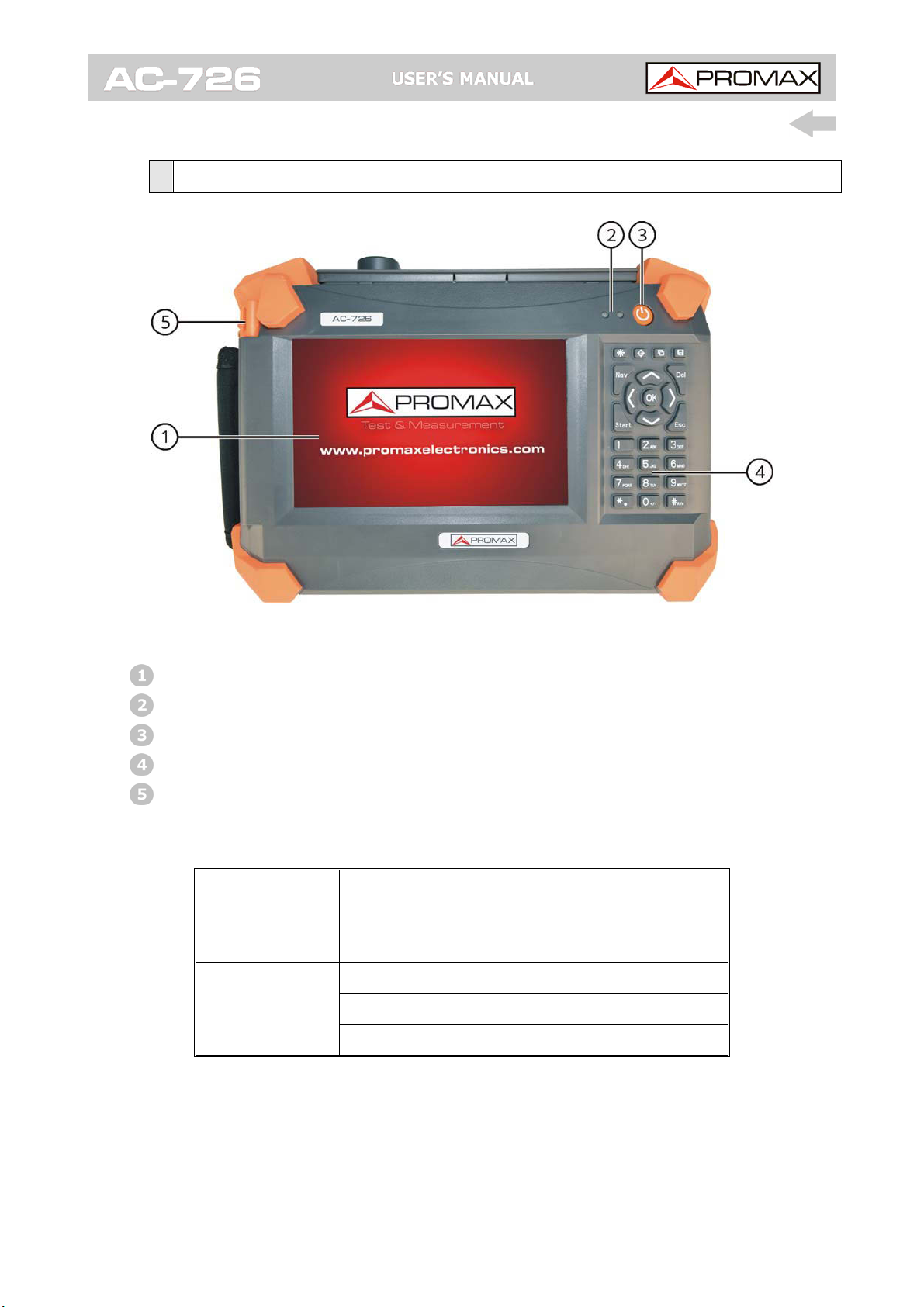
Description for hard keyboard:
Adjust the display screen brightness, there are four
levels.
Switch display mode (black and white, normal, night
vision, and high contrast).
Preview, save the measurement picture.
Save calibration and measurement curve.
Popup or down the right menu.
Quick start measurement.
Backspace.
Return to the previous interface.
Left and right move marker line.
Up and down move limit line.
Enter key.
Digital key, input 0-9.
* Decimal point.
# Minus sign.

9 April 2016
3 USER INTERFACE AND MENU INSTRUCTIONS
3.1 Turn on the instrument
Press , equipment will display the boot picture. During startup, the right light
turns red, the system will initialize DSP system, self check system state, etc.
When main interface appear, the boot process end, the right light turns green.
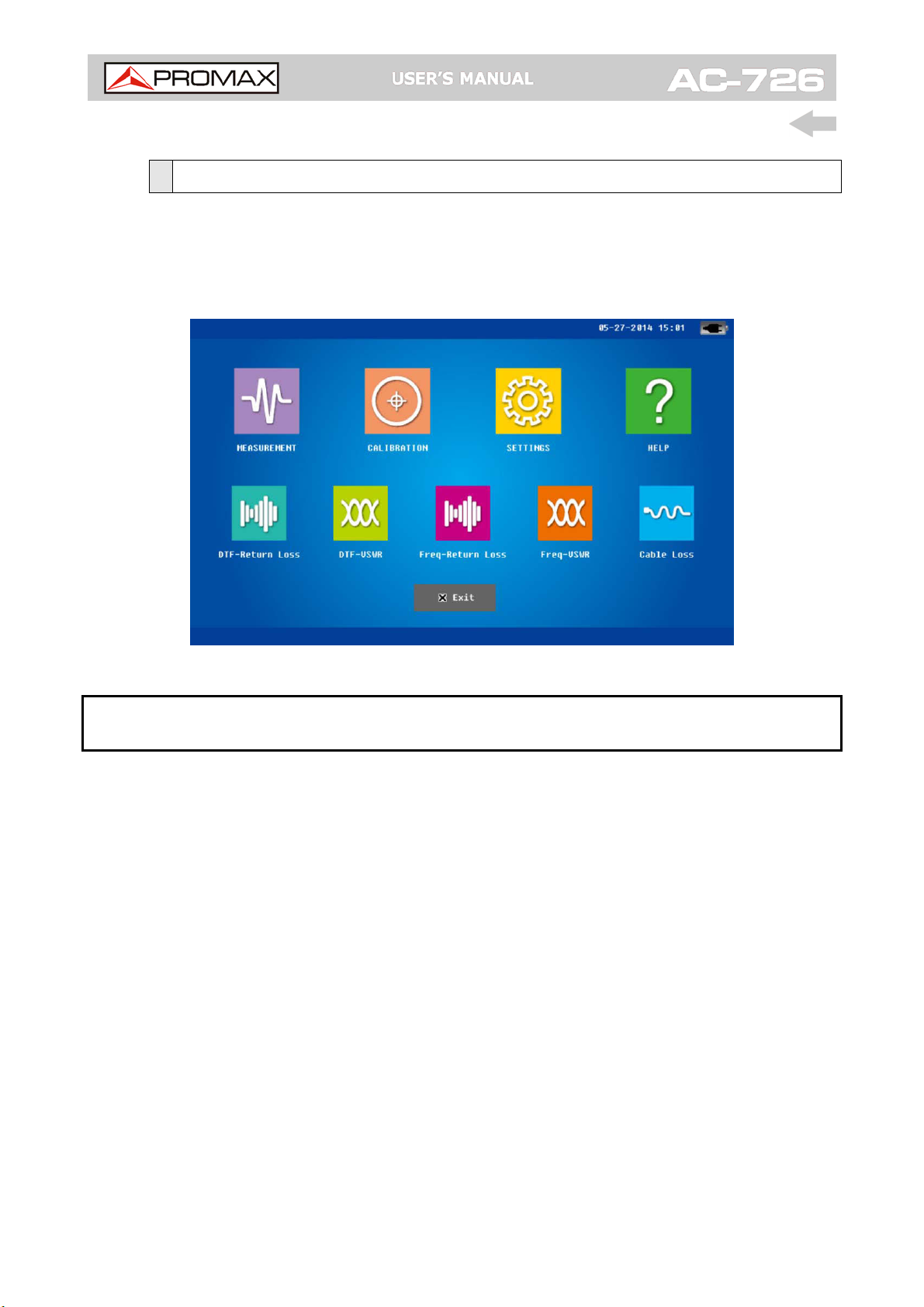
Figure 3.: Main interface

April 2016 10
3.2 Main interface
Click “MEASUREMENT” Icon, 5 sub-icons appear, corresponding to the five
measurement modes: DTF (distance fault) return loss, DTF-VSWR, Frequency
return loss, Frequency-VSWR, cable loss. Click the icon, the system will go into
the corresponding measurement interface.
Figure 4.: Main interface
NOTE: Click other icons in the main interface (CALIBRATION, SETTINGS, HELP),
system will enter the corresponding operation interface.
Table des matières
Manuels Instrument analytique populaires d'autres marques

EXTOL PREMIUM
EXTOL PREMIUM 8820043 Instructions d'installation et d'utilisation

RIDGID
RIDGID SeeSnake Compact Manuel utilisateur

Teledyne
Teledyne 3000PA Manuel utilisateur

YDLIDAR
YDLIDAR TIA Manuel utilisateur

Olympus
Olympus IPLEX FX Series Manuel utilisateur

Bosch
Bosch GLM 50 C Professional Manuel utilisateur