Proctor PCW 207R Manuel utilisateur

Full HD Mulple Streams Vandal Proof
Fixed Dome IP Camera
User’s Manual
Ver1.4

1
Table of Contents
1. Overview .................................................................................................................................. 2
1.1 Features ....................................................................................................................... . 2
1.2 Package Contents ......................................................................................................... 3
1.3 Dimensions.................................................................................................................... 5
1.4 Connectors .................................................................................................................... 6
2. Camera Cabling....................................................................................................................... 7
2.1 Connect Power.............................................................................................................. 7
2.2 Connect Ethernet Cable ................................................................................................ 7
2.3 Connect Alarm I/O......................................................................................................... 7
3. System Requirements ............................................................................................................ 8
4. Access Camera ....................................................................................................................... 9
5. Setup Video Resolution........................................................................................................ 13
6. Configuration Files Export/ Import...................................................................................... 20
Appendix A: Technical Specifications........................................................................................ 21
Appendix B: Delete the Existing DC Viewer............................................................................... 24
Appendix C: Setup Internet Security .......................................................................................... 25

2
1. Overview
Supported with both H.264 and MJPEG standar d, the product series not only
features in superior Full HD resolution for real-time streaming at 25/30 fps, but
also supplies D1 720p real-time streaming. With more comput ing power, the IP
Camera could provide more exibil ity for users and system managers.
1.1 Features
•Progressive Scan CMOS Sensor
•Dual Streams, Full HD real-time + D1 real-time
•H.264 and MJPEG compression
•Remote Zoom & Focus (Motorized Lens; Optional)
•Motion Detection
•Privacy Masks
•WDR
•Smart Picture Quality/3DNR
•Tampering Alarm
•Day/Night (ICR)
•Micro SD support
•BNC analog output
•IR LED module (Optional)
•Weatherproof (IP 66 International)
•Vandal Proof Dome Cover
•Sunshield & Outdoor Mounting Kit
•ONVIF Support

3
1.2 Package Contents
Please check the package contains the following items listed below.
Indoor Camera Package Contents
Vandal Proof
Fixed Dome IP Camera
DC Jack Cable
Power Terminal Block
Security Torx
Self Tapping Screws
(×4)
Plastic Screw Anchors
(×4)
Rubber Washers (×6)
CD
(bundled software and
documentation)
Quick Guide

4
Outdoor Camera Package Contents
Vandal Proof Fixed Dome
IP Camera
DC Jack Cable
Power Terminal Block Security Torx
Hexagon Screw-M8*12 (x1)
Spring Washer (×1)
Rubber Washer ( ×1)
Pendant Tube Washer (×1)
CD
(bundled software and
documentation)
Quick Guide

5
1.3 Dimensions
The IP Dome Camera’s dimensions are shown below.
Indoor
Top View Side View
Outdoor
Top View Side View

6
1.4 Connectors
The diagram below shows the IP Camera’s reset button and various connectors.
Denition for each connector will be given as follows.
No. Connector Pin Definition Remarks
1 Reset Button - Restore to factory default
2 BNC - Analog Video Output
1 GND (Input -)
2 Input+
3 Output-
3 Alarm I/O
4 Output+
Alarm connection
1 Output (L)
2 Output (R)
3 GND
4 Audio I/O
4 Input
Two-way audio transmission
1 Power
2 ReservedDC 12V
3 GND
1 Power-1
2 EarthGND
5 Power
AC 24V
3 Power-2
Power connection
6 RJ-45 - 10/100 Mbps Ethernet / PoE
7
2. Camera Cabling
Please follow the instructions below to complete IP Camera connection.
2.1 Connect Power
Please refer to Section: Connectors . Alternatively, connect the Ethernet cable to
the camera’s PoE port and plug the other end of the cable into a PoE switch.
NOTE: If using PoE, make sure Power Sourcing Equipment (PSE) is in
use in the network.
2.2 Connect Ethernet Cable
Use of Category 5 Ethernet cable is recommended for network connection; to
have best transmission quality, cable length shall not exceed 100 meters.
Connect one end of the Ethernet cable to the RJ-45 connector of the IP Dome
Camera, and the other end of the cabl e to the network switch or PC.
NOTE: In some cases, you may need us e an Ethernet crossover cable
when connecting the IP Dome Ca mera directly to the PC.
Check the status of the link indicator and ac tivity indicator LEDs; if the LEDs are
unlit, please check LAN connection.
Green Link Light indicates good network connection.
Orange Activity Light ashes for network activity indication.
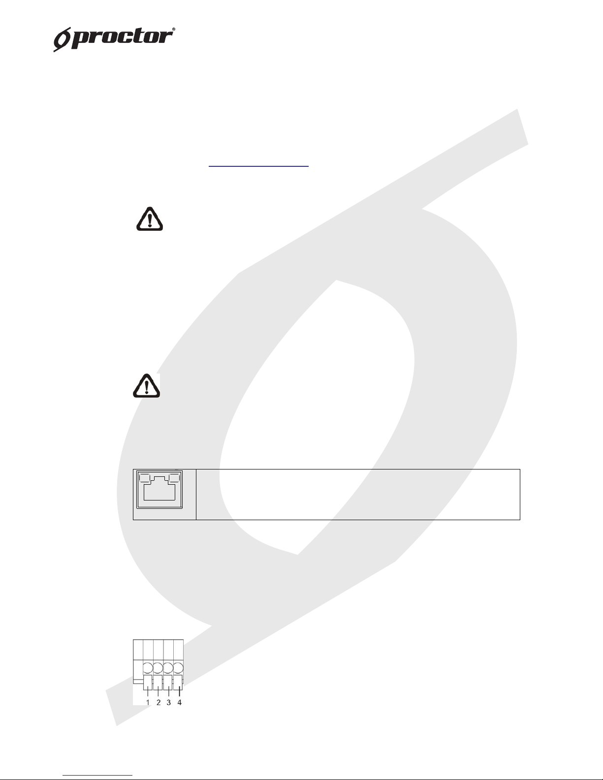
2.3 Connect Alarm I/O
The camera equips one alarm input and on e relay output for alarm application.
Refer to alarm pin denitio n below to connect alarm devi ces to the IP Camera if
needed.
PIN 1: GND (Input-)
PIN 2: Input+
PIN 3: Output-
PIN 4: Output+

8
3. System Requirements
To perform the IP Camera via web browse r, please ensure your PC is in good
network connection, and meet system requirements as described below.
Items System Requirement
Personal Computer
1. Intel ®Pentium ®M, 2.16 GHz or Intel ®Core TM 2 Duo, 2.0
GHz
2. 2 GB RAM or more
Operating System Windows VISTA / Windows XP / Windows 7
Web Browser Microsoft Internet Explorer 6.0 or later
Firefox
Chrome
Safari
Network Card 10Base-T (10 Mbps) or 100Base-TX (100 Mbps) operation
Viewer ActiveX control plug-in for Microsoft IE

9
4. Access Camera
For initial access to the IP Camera, users can sear ch the camera through the
installer program: DeviceSearch.exe, wh ich can be found in “DeviceSearch”
folder in the supplied CD.
Device Search Software Setup
Step 1: Double click on the program Device Search.exe. After its window
appears, click on the <Device Search> button on the top side.
Step 2: The security alert window will pop up. Click on <Unblock> to continue.
Device Search
Step 3: Click on <Device Search> again, and a ll the nding IP devices will be
listed in the page. The IP Camera’s default IP address is:
192.168.0.250.
Step 4: Double click or right click and sele ct <Browse> to access the camera
directly via web browser.
Step 5: Then the prompt window of reques t for entering default username
and password will appear for logi n to the IP Dome Camera.
The default login ID and passwor d for the Administrator are:
Login ID Password
Admin 1234
NOTE: ID and password are case sensitive.
NOTE: It is strongly advised that administrator’s password be
altered for the security concerns. Refer to Full HD Multiple
Streams IP Camera Menu Tree for further details.
Table des matières
Autres manuels Proctor Caméra IP


